01Megasonic Energy in Nanoscale Wet Cleaning
While chemical etching undercuts particles, high-frequency acoustic energy provides the mechanical detachment force needed to remove nanoscale particles without damaging delicate sub-2nm transistor structures (e.g., FinFETs or Gate-All-Around nanosheets).
Standard ultrasonic cleaning () creates violent transient cavitation bubbles that collapse with extreme force, destroying micro-structures. Advanced wet tools use Megasonic Frequencies ().
02Megasonic Transducer Hardware Architecture
Megasonic systems utilize Piezoelectric Transducers (Lead Zirconate Titanate, PZT) bonded to quartz or sapphire transmitters:
- Operating Frequency: Typically .
- Acoustic Streaming (Eckart & Schlichting Streaming): High-frequency sound waves attenuate rapidly in liquid, generating a continuous high-speed fluid jet () directly along the wafer surface.
- Controlled Cavitation: Megasonics suppresses violent transient cavitation while promoting stable cavitation micro-bubbles that gently oscillate, providing precise physical lift to detachment particles.
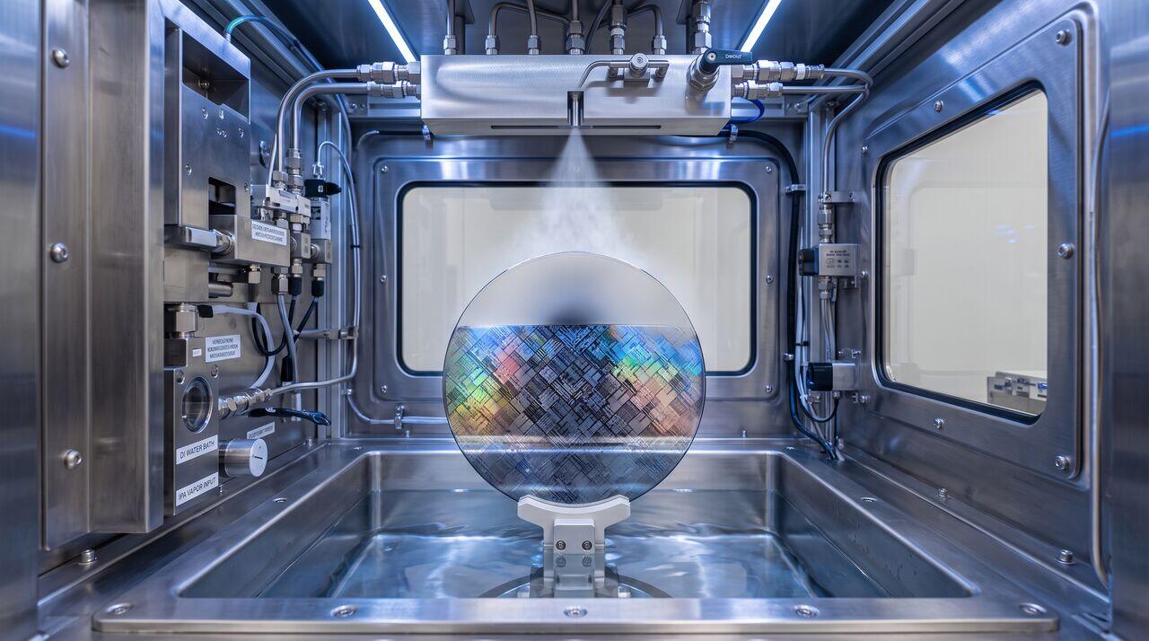
03Marangoni Drying Mechanics
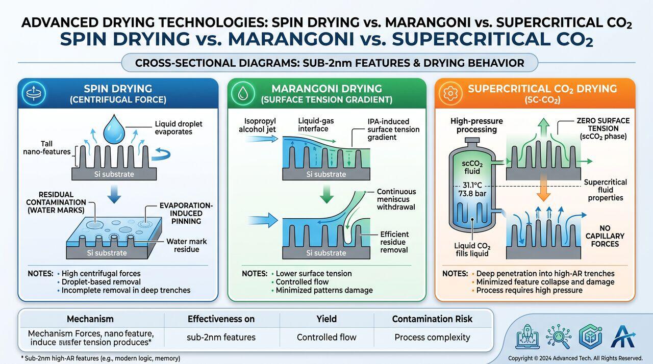
After wet cleaning and DIW rinsing, wafers must be dried with zero water marks. Simple spin drying leaves microscopic liquid droplets behind; as these droplets evaporate, dissolved silica precipitates to form destructive Water Mark Defects ( spots).
Fabs solve this using Marangoni Drying (Surface Tension Gradient Drying):
The Marangoni Effect
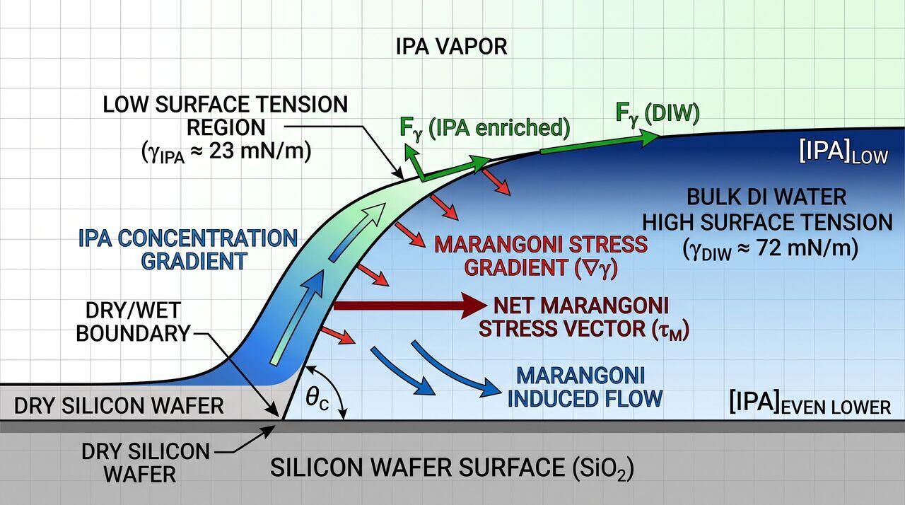
Isopropyl Alcohol (IPA) vapor mixed with nitrogen gas is introduced above the liquid meniscus as the wafer is slowly lifted from a DIW bath:
- IPA dissolves into the top liquid meniscus, lowering local surface tension ().
- The bulk DIW below maintains high surface tension ().
- This surface tension gradient () exerts a continuous upward pulling force on the liquid film, causing all water to drain completely off the wafer surface without leaving isolated droplets behind!
04Hardware Operating Window Summary
| Process Tool | Operational Parameter | Typical Target | Failure Mode if Out-of-Spec |
|---|---|---|---|
| Megasonic System | Frequency / Power | @ | Pattern collapse (power too high), Low PRE (too low) |
| Marangoni Dryer | Wafer Lift Velocity | Water film break / water mark spots | |
| IPA Vapor Delivery | IPA Flow Rate / Temp | @ | Condensation marks, organic residues |
→Prerequisites & continue reading
Prerequisites: Acoustics Basics, Surface Tension Principles
Also in Topic 4.3, Particle Removal & Zeta Potential Engineering:
Tier 1 · Particle Removal Physics & Zeta Potential Manipulati…Tier 3 · DLVO Theory, Acoustic Cavitation Dynamics & Supercri…