01Executive Summary
While Preston's equation provides a macro-scale framework for CMP, maintaining uniform material removal across a wafer requires precise control over non-uniform pressure fields and spatial velocity profiles. Modern CMP tools achieve sub-nanometer thickness non-uniformity (WIWNU ) by deploying multi-zone pneumatic carrier heads, synchronized platen-carrier rotation, and active retaining ring pressure compensation. This technical analysis explores the kinematic velocity distributions, multi-zone pressure control architectures, and mechanical shear dynamics of advanced oxide and polysilicon CMP tools.
02Mathematical Kinematics of Rotary CMP Systems
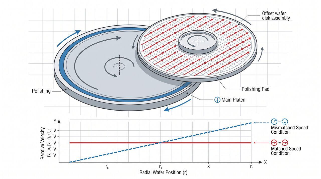
In a standard rotary CMP platform, both the polishing platen (radius , angular velocity ) and the wafer carrier head (radius , angular velocity ) rotate in the same direction.
The position vector of a point P on the wafer relative to the wafer center is . The position vector of the wafer center relative to the platen center is . The total relative velocity at point P between the wafer surface and the polishing pad is given by:
Expanding into scalar components in a Cartesian coordinate system aligned with the wafer center:
The magnitude of the relative linear velocity is:
The Synchronous Rotation Condition
When the carrier rotational speed equals the platen rotational speed ():
Crucial Insight: When , every single point across the entire wafer surface experiences the exact same magnitude of relative linear velocity relative to the pad, regardless of its radial distance from the wafer center. This synchronous rotation condition is the mathematical foundation of uniform removal in rotary CMP.
03Multi-Zone Pneumatic Carrier Head Mechanics
Even with uniform relative velocity, wafer thickness non-uniformity occurs due to edge stress concentrations, pad bending, and slurry depletion beneath the wafer. Modern carrier heads utilize pneumatic multi-zone membranes to apply independent pressure fields across radial zones.
Pressure Zone Functions
- Center Zone (): Compensates for slurry starvation in the wafer core.
- Middle/Inner-Annular Zones (): Maintains baseline removal across the majority of the wafer area.
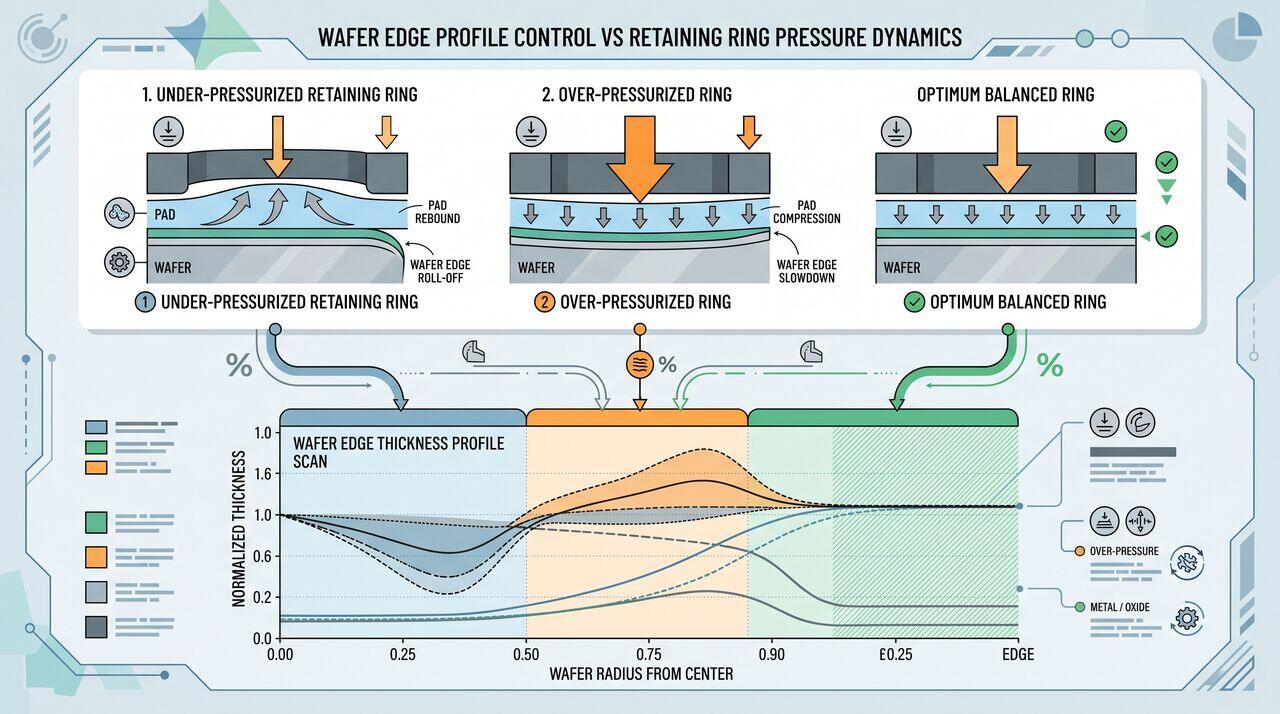
- Edge Zone (): Fine-tunes removal within of the wafer apex to prevent edge roll-off or edge slow-down.
- Retaining Ring Zone (): Pre-compresses the flexible polyurethane pad ahead of the wafer edge. If , the pad bulges up at the wafer edge, causing severe edge roll-off (over-polishing). If , the pad is over-compressed, causing edge slow-down.
04Prestonian Removal Rate Optimization Matrix
| Parameter | Increase Effect on MRR | Effect on Uniformity (WIWNU) | Effect on Defectivity | Operational Limit |
|---|---|---|---|---|
| Platen Speed () | Linear increase | Improves macro-uniformity | Increases pad thermal degradation | Slurry hydroplaning () |
| Down-Force () | Linear increase | Zone-dependent tuning | Increases micro-scratching & dishing | Structural dielectric damage () |
| Slurry Flow Rate | Asymptotic plateau | Improves edge-to-center heat transfer | Minimal impact on defects | Economic/chemical waste () |
| Retaining Ring Pressure | Neutral on bulk | Eliminates edge roll-off | Controls edge chipping | Mechanical seal wear & pad degradation |
→Prerequisites & continue reading
Prerequisites: ["p03-t3.1-t1-oxide-polysilicon-cmp-fundamentals"]
Also in Topic 3.1, Oxide & Polysilicon CMP:
Tier 1 · Oxide and Polysilicon CMP Fundamentals: Achieving Gl…Tier 3 · Tribology & Luo-Dornfeld Abrasive Mechanics: Micro-S…