01Introduction & Physical Intent
Deep Ultraviolet (DUV) immersion lithography, commonly known as 193i, represents one of the most remarkable engineering triumphs in semiconductor manufacturing. Before the advent of immersion technology, optical lithography using dry ArF (Argon Fluoride) excimer lasers operating at a wavelength (\(\lambda\)) of 193 nm hit a fundamental physical brick wall at the 45 nm technology node.
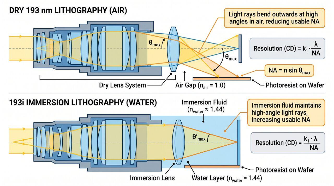
To project finer transistor features onto a silicon wafer, optical physics dictates that scanner systems must either decrease the light wavelength or increase the numerical aperture (\(\text{NA}\)) of the projection lens system. While shortening the wavelength below 193 nm proved extraordinarily difficult due to severe glass absorption in traditional optics, immersion lithography achieved a breakthrough by filling the narrow gap between the bottom lens element and the wafer surface with ultra-pure water (\(\text{H}_2\text{O}\)). Because water has a refractive index (\(n_{\text{water}} \approx 1.44\) at 193 nm) higher than air (\(n_{\text{air}} = 1.0\)), it effectively shortens the light wavelength inside the liquid, allowing the projection optics to capture higher-angle diffracted light rays and enabling an effective NA exceeding 1.0 (Hyper-NA, up to 1.35 NA).
02Key Process Inputs & Outputs
- Inputs:
- Light Source: Argon Fluoride (ArF) excimer laser emitting line-narrowed 193.3 nm UV light pulses.
- Immersion Fluid: Ultra-Pure Water (UPW) strictly degassed and temperature-controlled to within \(\pm 0.001^\circ\text{C}\).
- Reticle / Photomask: Quartz substrate with chrome or attenuated phase-shifting mask (AttPSM) features containing circuit patterns enlarged by 4x.
- Coated Substrate: Silicon wafer coated with a multi-layer stack: silicon substrate, bottom anti-reflective coating (BARC), and a hydrophobic 193i photoresist (or topcoat).
- Outputs:
- Latent Image: High-contrast chemical concentration profile of photo-acid generators (PAG) in the photoresist film.
- Critical Dimension (CD) Uniformity: Nanoscale feature lines and spaces resolved down to 38 nm in single exposure (or < 10 nm with multi-patterning).
03The Rayleigh Resolution Criterion
The fundamental capability of any optical projection lithography system is governed by the classical Rayleigh Resolution Criterion:
Where:
- \(\text{CD}\) is the minimum resolvable feature size (Critical Dimension).
- \(k_1\) is a process-dependent factor reflecting photoresist quality, illumination symmetry, and computational lithography enhancement (the physical lower bound for single exposure is \(k_1 = 0.25\)).
- \(\lambda\) is the vacuum wavelength of the light source (193.3 nm).
- \(\text{NA}\) is the Numerical Aperture of the lens system, defined as \(\text{NA} = n \cdot \sin(\theta_{\text{max}})\), where \(n\) is the refractive index of the medium between the lens and wafer, and \(\theta_{\text{max}}\)\ is the maximum half-angle of light collected by the lens.
By replacing air (\(n=1.0\)) with ultra-pure water (\(n=1.44\)), the maximum effective numerical aperture jumped from a theoretical maximum of 1.0 (practically 0.93 in dry scanners) to \(\text{NA} = 1.35\), extending DUV optical lithography through multiple sub-20nm manufacturing nodes.
04Media Companion Prompts
Media Prompt 1 (Photorealistic Render)
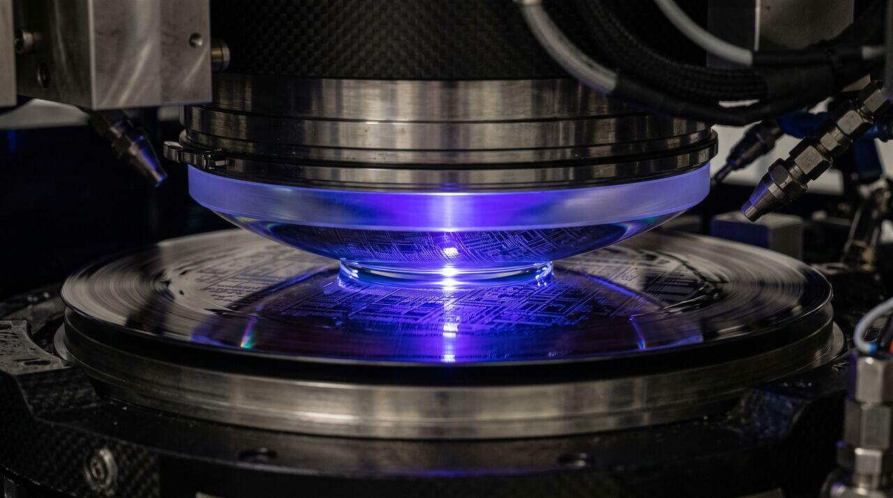
- Prompt: A dramatic, photorealistic close-up macro view inside a 193i DUV immersion scanner projection head. A crystal-clear water meniscus droplet is perfectly contained between the polished bottom element of a massive CaF2 quartz lens and a spinning silicon wafer coated with a glossy photoresist. A vibrant, deep ultraviolet blue laser beam passes through the lens and liquid, projecting intricate circuit patterns onto the wafer surface. High-tech cleanroom lighting, stainless steel and carbon-fiber mechanical components, 8k resolution, cinematic depth of field.
Media Prompt 2 (Technical Vector Diagram)
- Prompt: A clean vector graphic comparing dry 193 nm lithography vs. 193i immersion lithography optics. Shows light rays bending at the lens-air boundary in dry lithography versus light rays continuing at high angles through ultra-pure water (n=1.44) in immersion lithography. Annotations detail the Rayleigh criterion equation CD = k1 * lambda / NA, light cone angle theta, and refractive index labels.
Media Prompt 3 (Educational Infographic)
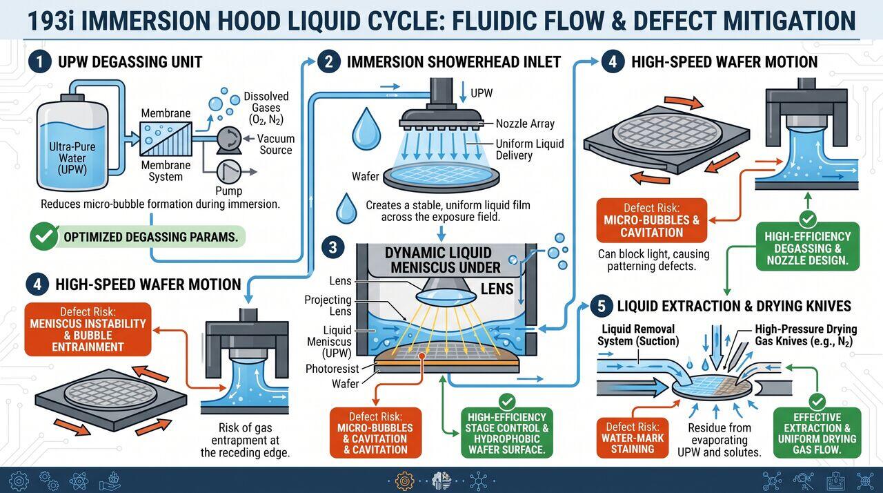
- Prompt: An educational infographic illustrating the 193i Immersion Hood liquid cycle. Shows a step-by-step fluidic flow diagram: UPW Degassing Unit -> Immersion Showerhead Inlet -> Dynamic Liquid Meniscus under Lens -> High-Speed Wafer Motion -> Liquid Extraction and Drying Knives. Highlights defect risks like micro-bubbles and water-mark staining with mitigation callouts.
→Prerequisites & continue reading
Prerequisites: ["p01-t1.1-t1-quartzite-to-mg-si-fundamentals"]
Also in Topic 5.1, DUV Immersion Lithography (193i):
Tier 2 · DUV Scanner Optics & Water Immersion Hood Mechanics…Tier 3 · Hyper-NA Fluid Dynamics, Polarization Effects & Line…