01Advanced Physical Principles & Vector Diffraction Theory
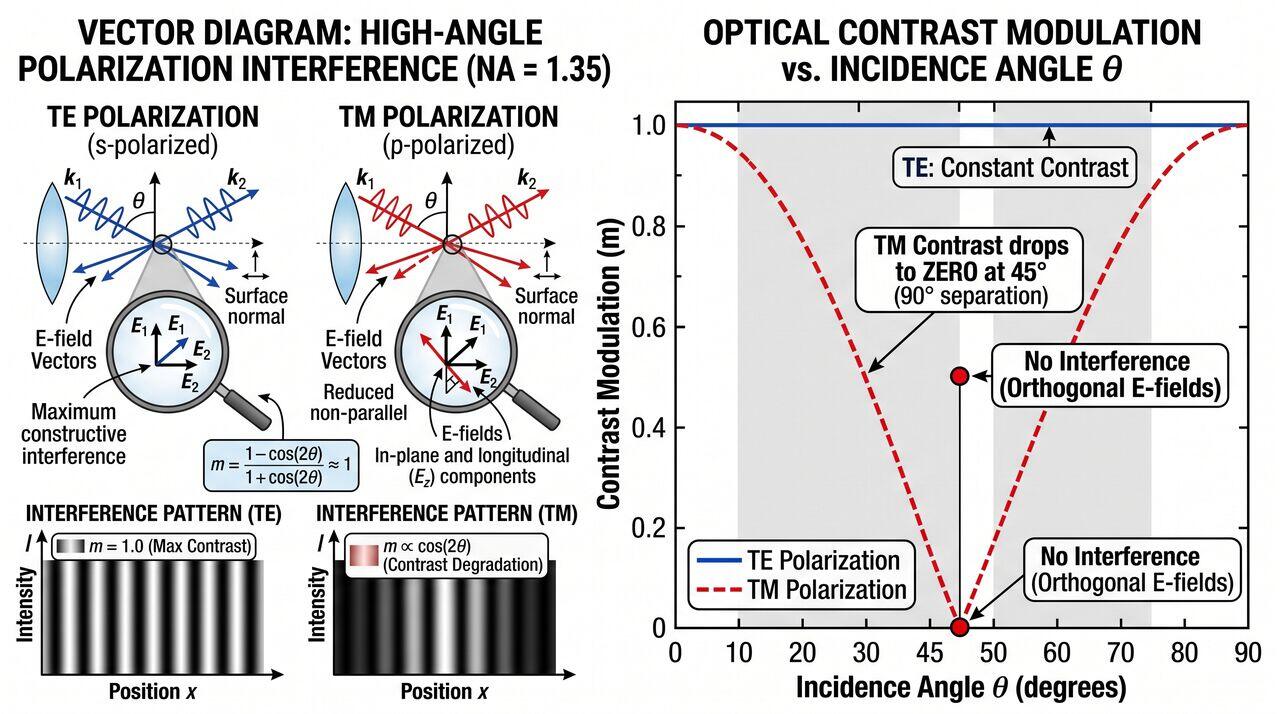
At Numerical Apertures exceeding 1.0 (Hyper-NA, up to \(\text{NA} = 1.35\)), the scalar wave approximation of light completely fails. Light rays exit the final lens element at extreme angles (\(\theta > 60^\circ\)) relative to the wafer normal. At these severe angles, the vectorial nature of the electric field becomes dominant, requiring full Vector Diffraction Theory to model image formation inside the photoresist stack.
When two light beams interfere at high angles to form a grating pattern:
- s-Polarization (Transverse Electric, TE): The electric field vectors of both intersecting beams are parallel to each other (pointing out of the page). Their dot product is independent of angle:
This yields maximum fringe contrast (100% modulation depth) regardless of the numerical aperture.
- p-Polarization (Transverse Magnetic, TM): The electric field vectors lie within the plane of incidence. As the half-angle \(\theta\) between beams approaches \(45^\circ\) (total intersection angle \(2\theta = 90^\circ\)), the electric field vectors become orthogonal:
At \(2\theta = 90^\circ\), \(\cos(90^\circ) = 0\), meaning TM-polarized light produces zero optical interference fringe contrast, completely washing out the printed image.
Polarization Control via Dipole/Quadrupole Illumination
To overcome TM contrast loss, modern 193i scanners utilize polarized illumination source shaping. By placing linear polarization rotators in the illuminator, light forming vertical line/space patterns is forced strictly into TE polarization, maintaining high Normalized Image Log-Slope (NILS) at \(\text{NA} = 1.35\).
02Mathematical Modeling & Hydrodynamic Boundary Layer Kinematics
2.1 Dynamic Contact Angle and Meniscus Instability
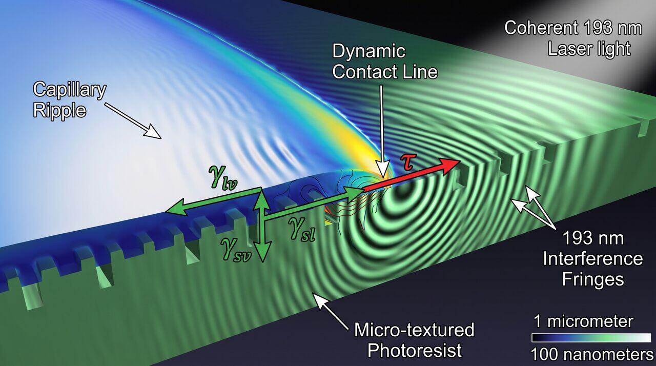
The movement of the immersion water meniscus across the photoresist surface during high-speed stage movement is governed by the Navier-Stokes equations modified for dynamic contact lines. The critical stage scanning velocity \(v_{\text{crit}}\)\ at which water droplet trailing occurs is modeled by the Capillary Number (Ca):
Where:
- \(\mu\) is the dynamic viscosity of ultra-pure water (\(\sim 1.0 \times 10^{-3}\text{ Pa}\cdot\text{s}\)).
- \(v\) is the wafer stage velocity (m/s).
- \(\gamma\) is the liquid-vapor surface tension of water (\(\sim 72.8\text{ mN/m}\)).
When the local Capillary Number exceeds a critical value, or when the receding contact angle \(\theta_{\text{rec}}\)\ drops below a hydrodynamic threshold (typically \(\theta_{\text{rec}} < 70^\circ\)), the air-water-resist three-phase contact line destabilizes, causing air entrainment (micro-bubbles) or fluid film breakup (trailing droplet defects).
03Line-Edge Roughness (LER) & Stochastic De-protection Physics
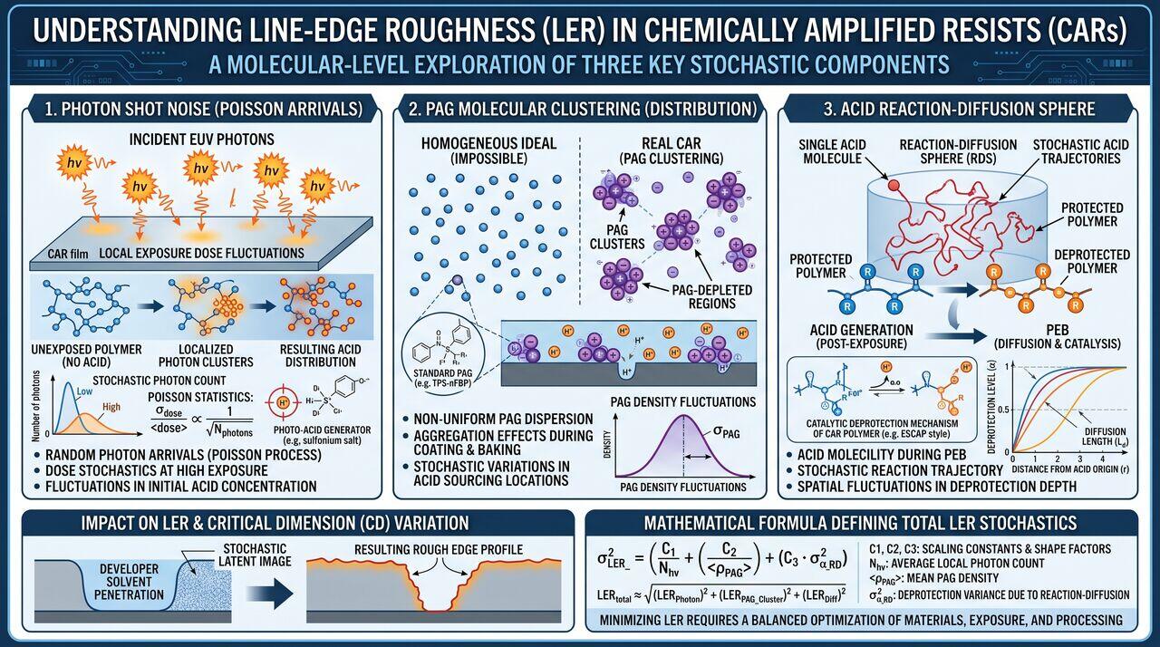
As feature sizes approach the sub-30 nm regime under 193i immersion multi-patterning, Line-Edge Roughness (LER) and Line-Width Roughness (LWR) become major yield killers. LER is driven by three coupled stochastic phenomena during chemical de-protection:
Total LER^2 = (Stochastic Photon Noise)^2 + (PAG Spatial Distribution Variance)^2 + (Acid Diffusion Blur)^2
- Shot Noise (Photon Statistics): Local fluctuation in the number of absorbed 193 nm photons follows a Poisson distribution:
- Photo-Acid Generator (PAG) Inhomogeneity: Microscopic chemical clustering of PAG molecules within the polymer matrix.
- Acid Diffusion Blur: During Post-Exposure Bake (PEB), photo-acids diffuse isotropically according to Fick's Law, smoothing out high-frequency noise but blurring the chemical edge gradient:
04Media Companion Prompts
Media Prompt 1 (Photorealistic Render)
- Prompt: A high-speed scientific visualization of a fluidic meniscus dynamic contact line slipping over a textured polymer photoresist film. Highlighting micro-scale capillary wave ripples, vector force arrows representing surface tension gamma and dynamic shear stress, illuminated by coherent 193 nm laser light interference fringes inside the resist film. 8k resolution, photorealistic physics simulation style.
Media Prompt 2 (Technical Vector Diagram)
- Prompt: A vector diagram contrasting TE (Transverse Electric) vs TM (Transverse Magnetic) polarization interference at high angles (NA = 1.35). Shows E-field vector orientation arrows, wave interference pattern profiles, and a line plot of Optical Contrast Modulation vs. Incidence Angle theta, demonstrating the dropdown of TM contrast to zero at 45 degrees incidence.
Media Prompt 3 (Educational Infographic)
- Prompt: A comprehensive technical infographic detailing the three components of Line-Edge Roughness (LER) in Chemically Amplified Resists. Displays side-by-side molecular-level illustrations of: 1) Photon Shot Noise (Poisson arrivals), 2) PAG Molecular Clustering, and 3) Acid Reaction-Diffusion Sphere. Concludes with a mathematical formula box defining total LER stochastics.
→Prerequisites & continue reading
Prerequisites: ["p05-t5.1-t2-duv-scanner-optics-water-immersion-mechanics"]
Also in Topic 5.1, DUV Immersion Lithography (193i):
Tier 1 · DUV Immersion Lithography (193i): Fundamentals of Hi…Tier 2 · DUV Scanner Optics & Water Immersion Hood Mechanics…