01Tool Architecture & Sub-System Dynamics
Advanced 193i immersion scanners (such as ASML NXT Twin-Scan systems) represent some of the most complex electro-mechanical machines ever built. To achieve a wafer throughput exceeding 250 wafers per hour while maintaining sub-nanometer overlay accuracy, the scanner integrates four critical technological pillars:
1.1 Catadioptric Lens Architecture
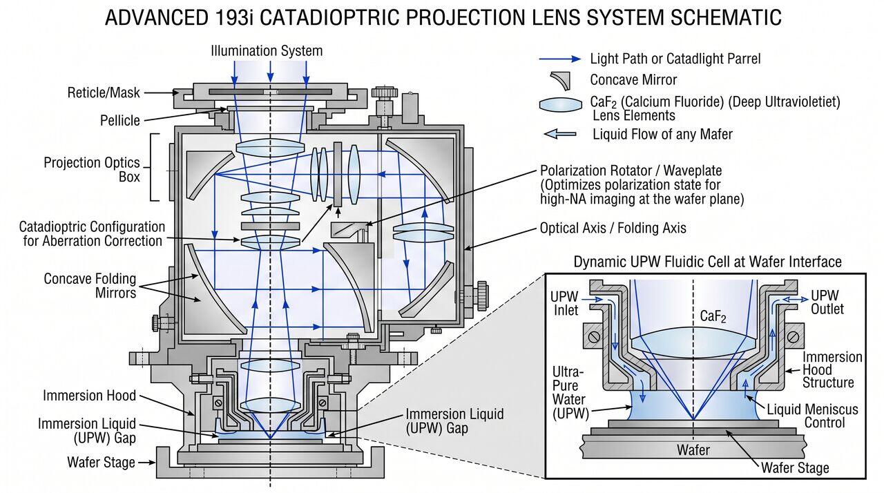
At Hyper-NA (\(\text{NA} = 1.35\)), pure dioptric (refractive lens only) projection systems become prohibitively large, requiring glass elements exceeding 1 meter in diameter that suffer from severe thermal lens heating and polarization distortion. 193i scanners solve this by employing catadioptric optics, which combine refractive lenses with concave mirrors. The mirror elements provide high optical power without chromatic aberration, folding the optical path into a compact inline barrel.
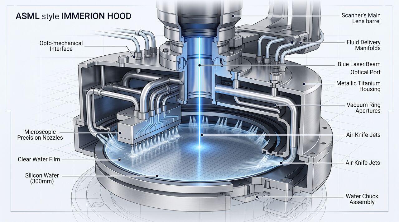
1.2 The Immersion Hood (IH) Assembly
The Immersion Hood (or Immersion Head) is a localized showerhead-like fluidic enclosure positioned immediately beneath the final lens element (the Last Lens Element, or LLE, typically constructed from single-crystal Calcium Fluoride, \(\text{CaF}_2\)).
- Liquid Containment: The IH maintains a stable water droplet (1–2 mm thick) strictly localized beneath the lens while the wafer stage scans beneath it at velocities exceeding 500–700 mm/s.
- Fluid Circulation: Fresh Ultra-Pure Water (UPW) is continuously injected through micro-porous showerheads and simultaneously extracted via vacuum suction channels to prevent thermal heating and chemical contamination build-up.
- Air Knives: High-velocity air curtains surrounding the extraction ring prevent water droplets from trailing off the moving wafer surface.
02Ultra-Pure Water (UPW) Chemical & Thermal Control
Because light passes directly through the water layer, any variation in water density, temperature, or chemical purity severely degrades pattern resolution:
| Parameter | Operational Specification | Process Failure Mode if Violated |
|---|---|---|
| Temperature Stability | \(\pm 0.001^\circ\text{C}\) (1 mK) | Refractive index fluctuation (\(dn/dT\)), causing focus drift |
| Dissolved Oxygen (DO) | \(< 1.0\text{ ppb}\) | Micro-bubble formation during optical laser cavitation |
| Dissolved Nitrogen (DN) | \(< 1.0\text{ ppb}\) | Bubble outgassing under localized pressure drops |
| Total Organic Carbon (TOC) | \(< 1.0\text{ ppb}\) | Lens contamination and photoresist leaching |
| Bacteria / Particulates | Zero particles \(> 20\text{ nm}\) | Direct printing defects and light scattering |
03Operational Mechanics & Defect Mitigation
3.1 Water Marks and Leaching
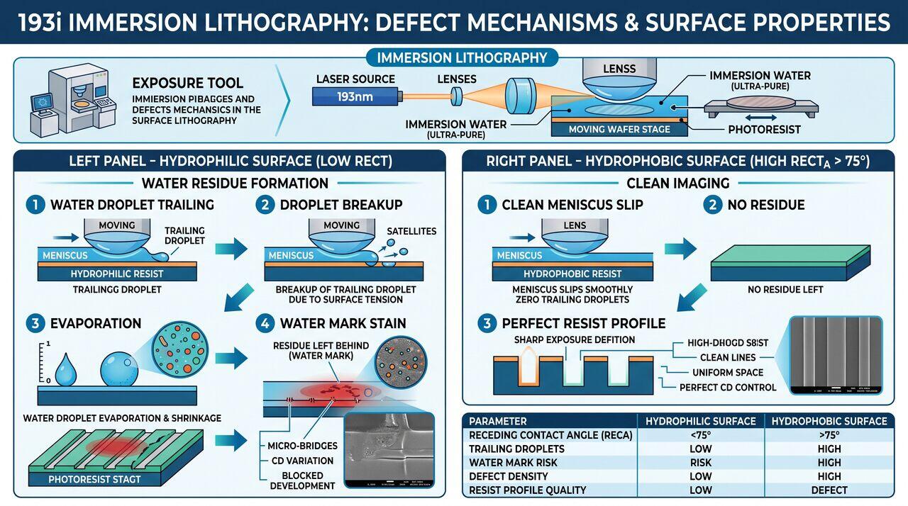
When the high-speed wafer stage moves beneath the immersion hood, the trailing edge of the liquid meniscus can leave behind microscopic water droplets if the photoresist surface is not sufficiently hydrophobic.
- Water Mark Defect: As a trapped droplet evaporates, non-volatile organic compounds or dissolved photo-acid components precipitate, forming an insoluble ring-like stain known as a water mark.
- Mitigation: Topcoat materials or topcoat-free photoresists are engineered with a high receding contact angle (\(\theta_{\text{rec}} > 75^\circ\)) to ensure the meniscus slips cleanly across the wafer without droplet breakup.
3.2 Micro-Bubbles
Microscopic gas bubbles suspended within the immersion fluid act as miniature spherical lenses, scattering 193 nm light and producing severe circular printing voids ("cold spots").
- Mitigation: Continuous inline vacuum degassing of UPW combined with controlled acoustic vibration prevents gas nucleation within the immersion hood showerhead.
04Media Companion Prompts
Media Prompt 1 (Photorealistic Render)
- Prompt: A detailed technical 3D render of an ASML-style immersion hood showerhead assembly positioning a liquid water film over a silicon wafer. Shows microscopic precision nozzles injecting clear water while surrounding vacuum ring apertures pull fluid upwards. Air-knife jets seal the outer boundary. High contrast industrial engineering aesthetic, metallic titanium housing, illuminated blue laser beam focused through the central optical port.
Media Prompt 2 (Technical Vector Diagram)
- Prompt: A technical schematic of a catadioptric projection lens system for a 193i scanner. Illustrates light paths reflecting off concave folding mirrors and passing through CaF2 lens elements down to the immersion hood. Annotations highlight the optical folding axis, polarization rotator, and the dynamic UPW fluidic cell at the wafer interface.
Media Prompt 3 (Educational Infographic)
- Prompt: A defect mechanism infographic for 193i immersion lithography. Shows two contrasting panels: Left Panel - Hydrophilic Surface showing water droplet trailing, droplet breakup, evaporation, and resulting water mark stain. Right Panel - Hydrophobic Surface (Receding Contact Angle > 75 degrees) showing clean meniscus slip, zero droplet residue, and perfect resist profile.
→Prerequisites & continue reading
Prerequisites: ["p05-t5.1-t1-duv-immersion-193i-lithography-fundamentals"]
Also in Topic 5.1, DUV Immersion Lithography (193i):
Tier 1 · DUV Immersion Lithography (193i): Fundamentals of Hi…Tier 3 · Hyper-NA Fluid Dynamics, Polarization Effects & Line…