01Laser-Produced Plasma (LPP) Source Architecture
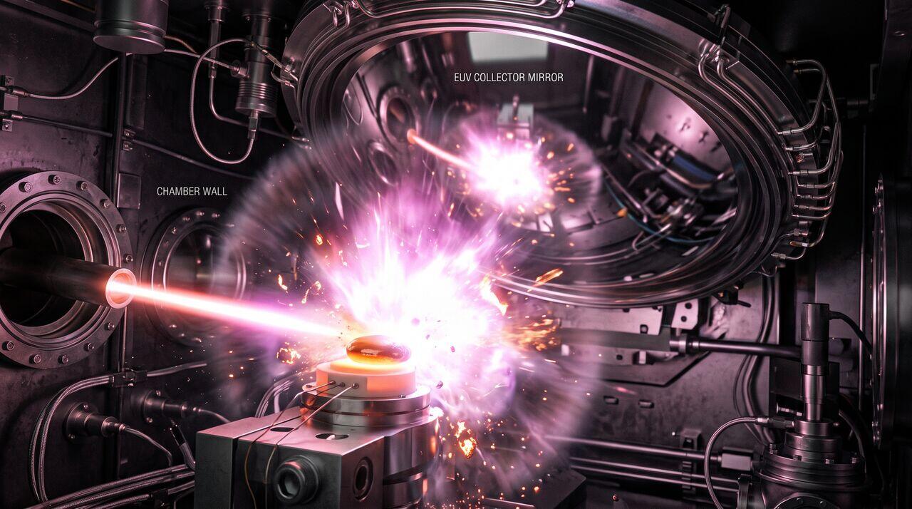
Generating sufficient 13.5 nm EUV light power to maintain commercial wafer throughput (> 160 wafers/hour) is one of the most extreme physics challenges in industrial manufacturing. At 13.5 nm, traditional light bulbs or arc lamps do not exist; light must be created by ionizing tin (Sn) into a highly charged plasma state.
1.1 Dual-Pulse Laser Engagement
- Droplet Injection: A precision piezo-driven droplet generator squirts microscopic molten tin droplets (\(30\ \mu\text{m}\) diameter) into the vacuum chamber at velocities of 80 m/s at a frequency of 50,000 Hz.
- Prep-Laser Pulse: A low-energy laser pulse hits the falling tin droplet, spreading it via thermal expansion into a thin, uniform "pancake" shape.
- Main-Laser Pulse: Nanoseconds later, a high-power \(20\text{ kW}\) pulsed \(\text{CO}_2\) industrial laser (wavelength \(10.6\ \mu\text{m}\)) blasts the tin pancake, heating it to temperatures exceeding 500,000 Kelvin (10 times hotter than the surface of the Sun).
- Ionization: At this extreme temperature, tin atoms strip down to \(\text{Sn}^{12+}\) through \(\text{Sn}^{14+}\) ionic states, emitting intense isotropic 13.5 nm EUV radiation via atomic electron transitions.
02Reflective Optics: Molybdenum/Silicon (Mo/Si) Bragg Multilayers
Because no optical glass transmits 13.5 nm light, all optical elements in an EUV scanner are specialized reflective mirrors.
2.1 Destructive vs. Constructive Interference Mechanics
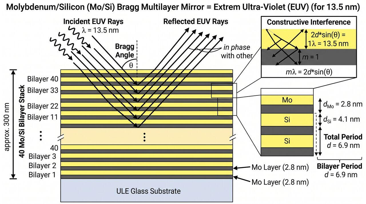
A single Mo/Si interface reflects only a tiny fraction of 13.5 nm light. By stacking 40 to 50 alternating layer pairs of Molybdenum (\(2.8\text{ nm}\)) and Silicon (\(4.1\text{ nm}\)) with a precise periodic thickness \(d \approx 6.9\text{ nm}\), constructive interference occurs according to Bragg's Law:
Even with sub-atomic deposition control, each Mo/Si mirror reflects a maximum of \(\sim 69\%\) of the incident EUV light, absorbing the remaining 31% as heat. Because a High-NA scanner contains up to 10-12 reflective mirrors in its optical train, total system light transmission drops to:
This low optical efficiency explains why \(20-30\text{ kW}\) of input laser power is required at the source to deliver a few hundred watts of EUV power to the wafer.
03High-NA Anamorphic Optics & Pellicle Mechanics
3.1 Why Anamorphic (4x / 8x) Scaling is Required
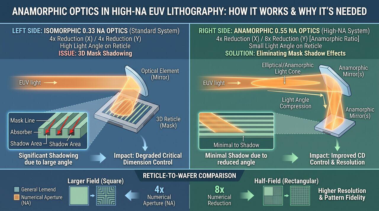
In standard 0.33 NA EUV systems, light hits the reticle at an incidence angle of \(6^\circ\). At 0.55 High-NA, the larger light cone forces the incidence angle on the reticle to increase to \(11-12^\circ\). At this steep angle, the high 3D feature structures on the mask would cast severe shadows over adjacent lines, ruining pattern fidelity.
To solve this without shrinking the overall physical reticle field size, High-NA EUV introduces Anamorphic Optics:
- Horizontal (X-axis): 4x reduction factor.
- Vertical (Y-axis): 8x reduction factor.
This asymmetric reduction reduces the light angle specifically along the scanning direction, completely eliminating mask 3D shadow degradation while requiring the wafer stage to scan at double the speed (10 m/s^2 acceleration).
04Media Companion Prompts
Media Prompt 1 (Photorealistic Render)
- Prompt: A high-speed macro photograph style 3D render capturing the exact microsecond moment a high-power CO2 laser blast ionizes a flattened molten tin droplet inside an EUV plasma chamber. Shows intense bright magenta-white plasma discharge, thermal shockwaves, and the huge parabolic ellipsoidal collector mirror gathering the emitted soft X-ray light. Metallic, high-vacuum industrial aesthetic.
Media Prompt 2 (Technical Vector Diagram)
- Prompt: A technical cross-sectional diagram of a Molybdenum/Silicon (Mo/Si) Bragg Multilayer mirror stack. Shows 40 alternating pairs of 2.8 nm Mo and 4.1 nm Si layers on an Ultra-Low Expansion glass substrate. Illustrates incident 13.5 nm EUV light rays reflecting off each layer interface and constructively interfering according to Bragg's Law m * lambda = 2d sin(theta).
Media Prompt 3 (Educational Infographic)
- Prompt: An educational infographic explaining Anamorphic Optics in High-NA EUV lithography. Features a side-by-side comparison: Left Side - Isomorphic 0.33 NA Optics (4x X / 4x Y scaling, showing 3D reticle line shadowing). Right Side - Anamorphic 0.55 NA Optics (4x X / 8x Y scaling, showing light angle compression eliminating mask shadow effects).
→Prerequisites & continue reading
Prerequisites: ["p05-t5.2-t1-euv-lithography-033na-055na-fundamentals"]
Also in Topic 5.2, EUV & High-NA EUV Lithography:
Tier 1 · Extreme Ultraviolet (EUV) Lithography: Fundamentals …Tier 3 · High-NA Anamorphic Optics, Mask 3D Effects & EUV Fla…