01Hardware Demands for Atomic Precision
While conventional RIE chambers maintain steady-state gas flows and continuous RF plasma discharges for minutes at a time, Atomic Layer Etching (ALE) tools must execute hundreds of discrete, highly synchronized chemical cycles within tight timeframes.
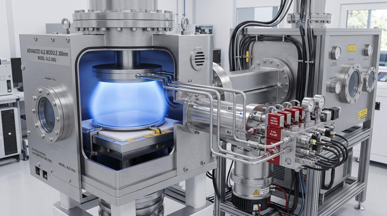
To make ALE commercially viable in high-volume manufacturing (HVM), tool manufacturers (such as Lam Research, Applied Materials, and TEL) engineered specialized hardware capabilities:
02Fast-Switching Gas Delivery & Chamber Purge Kinematics
The overall throughput of an ALE process is dominated by the duration of the purge steps (Step 2 and Step 4). If gas purging takes 5 seconds per step, a 100-cycle etch sequence requires over 15 minutes per wafer.
CONVENTIONAL RIE GAS PANEL ADVANCED ALE FAST-PULSE PANEL
Gas Flow: Continuous (sccm) Gas Flow: Millisecond Injections
Chamber Residence: ~1-3 sec Chamber Residence: < 100-200 ms
Key Hardware Innovations
- Ultra-Fast ALD-Style Injector Valves: Piezoelectric or high-speed solenoid pulse valves deliver precise chemical micro-doses with response times under .
- Cross-Flow Small-Volume Chambers: Reduced internal chamber volume () combined with high-capacity turbomolecular pumps enables complete gas exchange in under .
- Pulsed Inert Sweep Systems: High-velocity argon sweep flows continuously clear unreacted species from dead-volume zones near showerhead ports.
03Ion Energy Window Tuning & Synchronized RF Bias
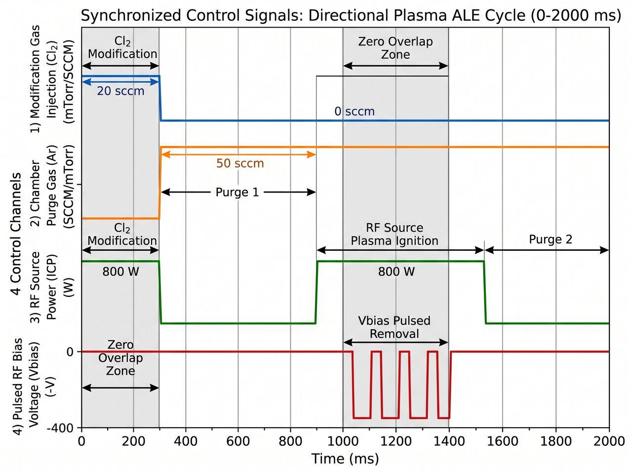
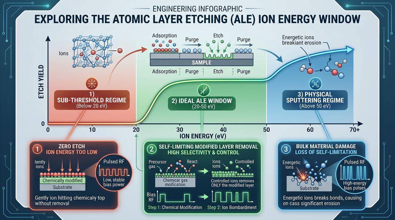
The critical challenge in Directional Plasma ALE is maintaining ion kinetic energies strictly within the ALE Operating Window:
Precise Energy Control
- Low-Frequency Bias Pulsing: RF bias power supplied to the wafer pedestal is pulsed in millisecond bursts during Step 3, producing an narrow Ion Energy Distribution Function (IEDF) centered between and .
- ICP Source Synchronization: The top ICP source plasma is maintained at low power to provide uniform ions without generating energetic high-voltage ions that would breach the bulk sputter threshold.
→Prerequisites & continue reading
Prerequisites: ["p06-t6.2-t1-atomic-layer-etching-ale-fundamentals"]
Also in Topic 6.2, Atomic Layer Etching:
Tier 1 · Atomic Layer Etching (ALE): Core Principles & Sub-Na…Tier 3 · Directional Plasma vs. Thermal Isotropic ALE: Surfac…