01Surface Thermochemistry of Directional Plasma ALE
Directional Plasma ALE relies on modifying the surface layer to lower its binding energy relative to the underlying bulk lattice. Consider the classic plasma ALE of silicon () using chlorine () and low-energy argon ions ():
Reaction Kinetics
- Modification Step: Molecular chlorine () dissociatively chemisorbs on bare silicon surfaces, forming a chlorinated surface complex (, where ). This reaction is self-limiting because does not spontaneously react with or diffuse into bulk silicon at room temperature:
- Binding Energy Shift: The formation of weakens the underlying back-bonds. The threshold energy required to sputter a atom drops from (pristine silicon lattice) down to for the chlorinated surface monolayer ().
- Removal Step: Bombarding the surface with ions at selectively sputters as volatile and species while leaving the underlying pristine silicon lattice unetched.
02Reaction Kinetics of Thermal Isotropic ALE: Fluorination & Ligand Exchange
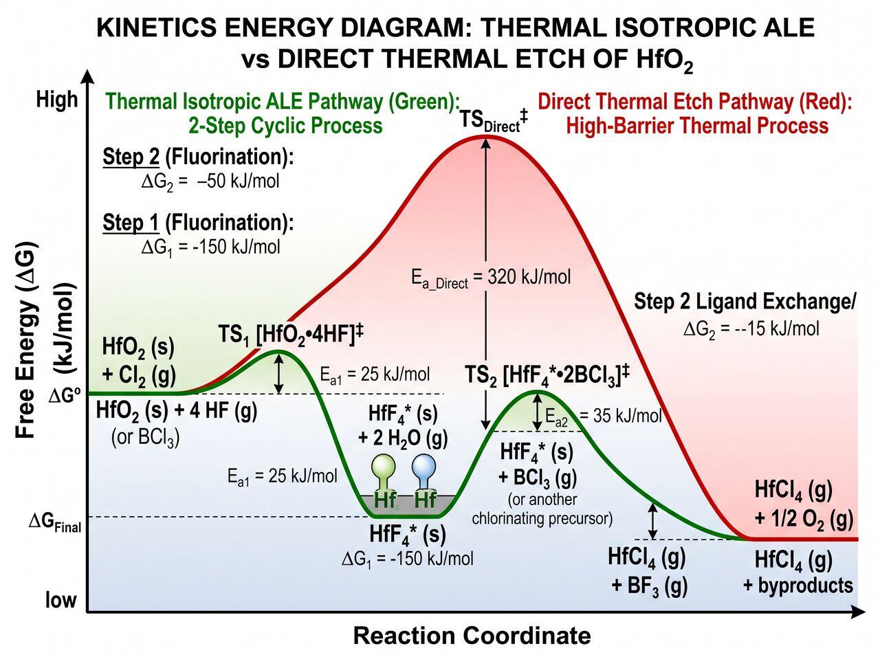
Thermal Isotropic ALE achieves conformal material removal without ion bombardment by leveraging sequential, self-limiting thermochemical reactions, most commonly Fluorination followed by Ligand Exchange.
Mechanism Example: Thermal ALE of Hafnium Oxide ()
Using hydrogen fluoride () and titanium tetrachloride () at :
- Fluorination (Step 1): Hydrogen fluoride gas converts the surface monolayer of into an insoluble hafnium tetrafluoride () layer:
- Ligand Exchange (Step 2): Titanium tetrachloride () is introduced. A transmetalation ligand-exchange reaction occurs where chloride ligands from swap with fluoride ligands on , forming volatile metal complexes ( and ) that desorb into the gas phase:
Because cannot directly react with the underlying un-fluorinated bulk oxide, the reaction terminates automatically once the surface monolayer is consumed.
03Advanced Applications: Gate-All-Around (GAA) Sacrificial SiGe Release
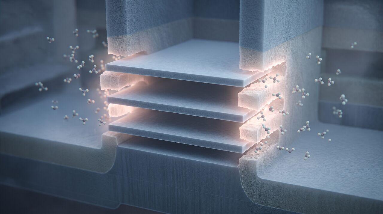
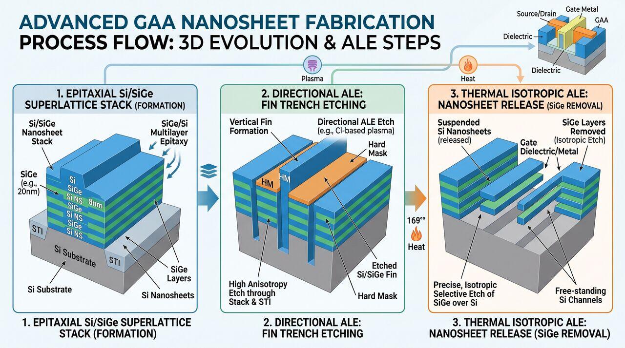
In sub-2nm GAA Nanosheet Transistor fabrication, horizontal silicon nanosheets are stacked alternately with sacrificial Silicon-Germanium () layers.
Thermal Isotropic ALE selectively removes the layers relative to with extreme selectivity (), creating sub-10nm suspension channels for gate oxide deposition without causing mechanical collapse or surface roughening of the delicate silicon channels.
→Prerequisites & continue reading
Prerequisites: ["p06-t6.2-t2-ale-tool-mechanics-gas-pulsing-plasma-cycles"]
Also in Topic 6.2, Atomic Layer Etching:
Tier 1 · Atomic Layer Etching (ALE): Core Principles & Sub-Na…Tier 2 · ALE Tool Architecture: High-Speed Gas Pulsing, Fast-…