01Advanced Hardware Demands for Deep Feature Etching
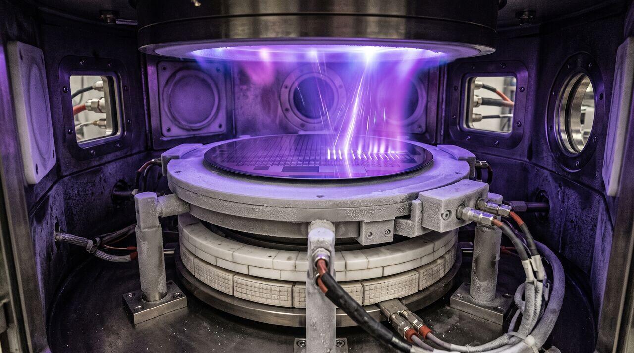
To overcome transport blockades and etch through deep 3D NAND channel holes or deep silicon TSVs, conventional RIE tool designs are insufficient. Fabs rely on specialized High-Aspect-Ratio (HAR) Etch Platforms incorporating two transformative hardware technologies:
02Cryogenic Sub-Zero Wafer Cooling Mechanics
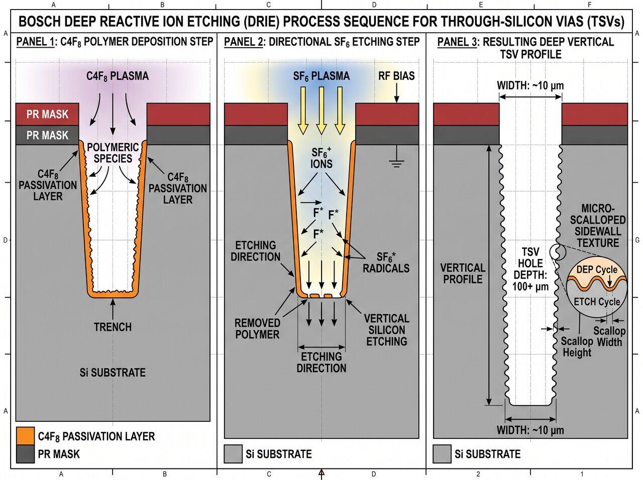
In standard dielectric etching, wafer temperatures are maintained between and . However, at these temperatures, fluorocarbon polymer passivation films on trench sidewalls desorb or erode rapidly under continuous ion exposure, causing severe trench bowing (widening of the upper trench).
Cryogenic Advantages
- Ultra-Thin Condensed Passivation: Cooling the wafer to or using specialized liquid nitrogen or fluorinert chiller units allows fluorine-based passivation species () to condense into a robust, ultra-thin protective film along vertical sidewalls.
- Radical Suppression: Spontaneous isotropic chemical etching on sidewalls is thermally frozen out, enabling purely ion-driven vertical removal at the trench bottom.
03High-Voltage Pulsed RF Power & Bias Waveform Shaping
To drive positive ions down an deep trench without significant angular deflection, ions require extreme directional kinetic energy. Modern HAR etchers utilize high-power bias generators capable of delivering peak RF voltages exceeding to .
Synchronized Bias Pulsing
- State-ON (High Bias Voltage): Accelerates ions vertically with high momentum, enabling them to punch through charge barriers and reach the deep trench bottom.
- State-OFF (Zero Bias): Allows accumulated positive electrostatic surface charge at the trench bottom to dissipate via low-energy electron arrival, eliminating notching and twisting defects.
04The Bosch Process for Deep Silicon TSV Etching
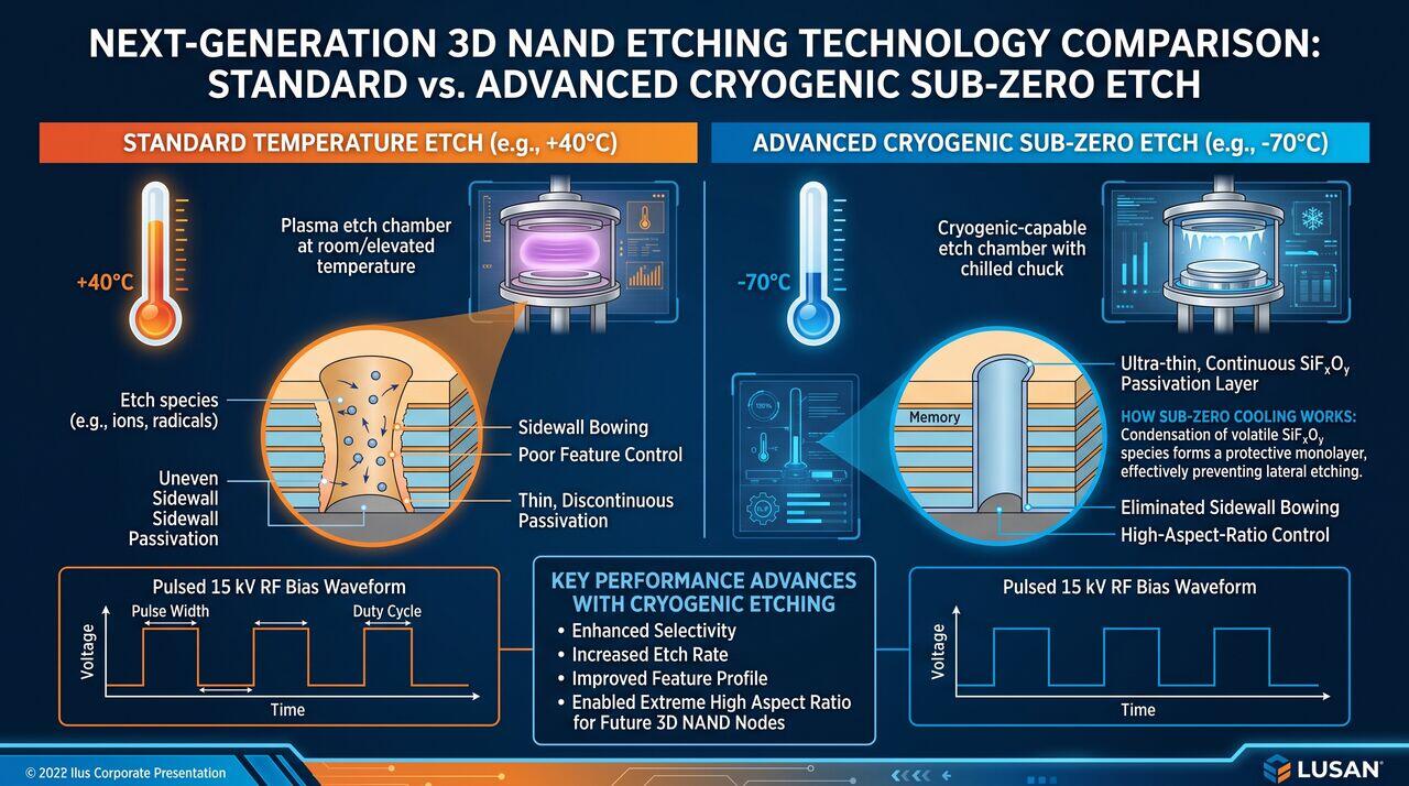
For deep Through-Silicon Vias ( wide silicon features), tools utilize the specialized Bosch Deep Reactive Ion Etching (DRIE) pulsed process:
→Prerequisites & continue reading
Prerequisites: ["p06-t6.3-t1-high-aspect-ratio-har-etching-fundamentals"]
Also in Topic 6.3, High-Aspect-Ratio Plasma Etching:
Tier 1 · High-Aspect-Ratio (HAR) Plasma Etching: Core Princip…Tier 3 · Deep-Trench Ion Transport, ARDE Modeling, Striation …