01Tool Hardware & Chamber Architecture
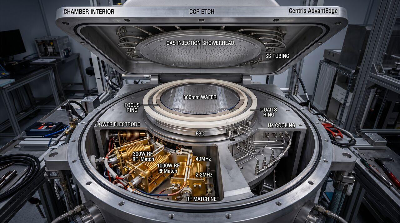
Modern plasma etch chambers are complex mechatronic systems designed to maintain precise vacuum levels, uniform RF field distributions, and tightly controlled chemical gas environments.
Key Subsystems
- RF Power Supply & Matching Networks: Delivers high-power RF energy (typically , , or ) through automated impedance matching networks containing variable vacuum capacitors and inductors to minimize reflected power.
- Gas Injection System: Multi-zone showerheads or tuned gas injection rings distribute process gases (, , , , , , ) uniformly over the wafer.
- Electrostatic Chuck (ESC): Bipolar or monopolar ceramic ESC clamps the wafer using electrostatic forces () while helium backside cooling maintains wafer temperature stability () under heavy plasma heat loads.
- Turbomolecular Vacuum Pumping: High-throughput turbomolecular pumps backed by dry mechanical pumps maintain chamber operating pressures between and .
02Decoupled Plasma Control: Independent Density vs. Energy Tuning
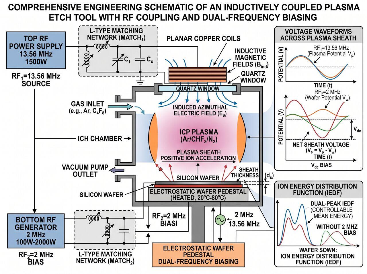
In single-frequency CCP systems, increasing RF power increases both plasma density (number of ions/radicals) and ion energy (sheath voltage). This coupling causes severe process trade-offs: high etch rates result in excessive mask erosion and substrate damage.
Modern ICP and Dual-Frequency CCP systems overcome this by decoupling generation:
- High Frequency (Source - e.g., 13.56 MHz / 60 MHz): Efficiently transfers energy to electrons, driving ionization and dissociation without creating high kinetic ion energies.
- Low Frequency (Bias - e.g., 400 kHz / 2 MHz): Ions can respond to the low-frequency RF cycle, experiencing strong directional acceleration across the sheath potential.
03Gas Phase Chemistry & Fluorocarbon Polymerization Balance
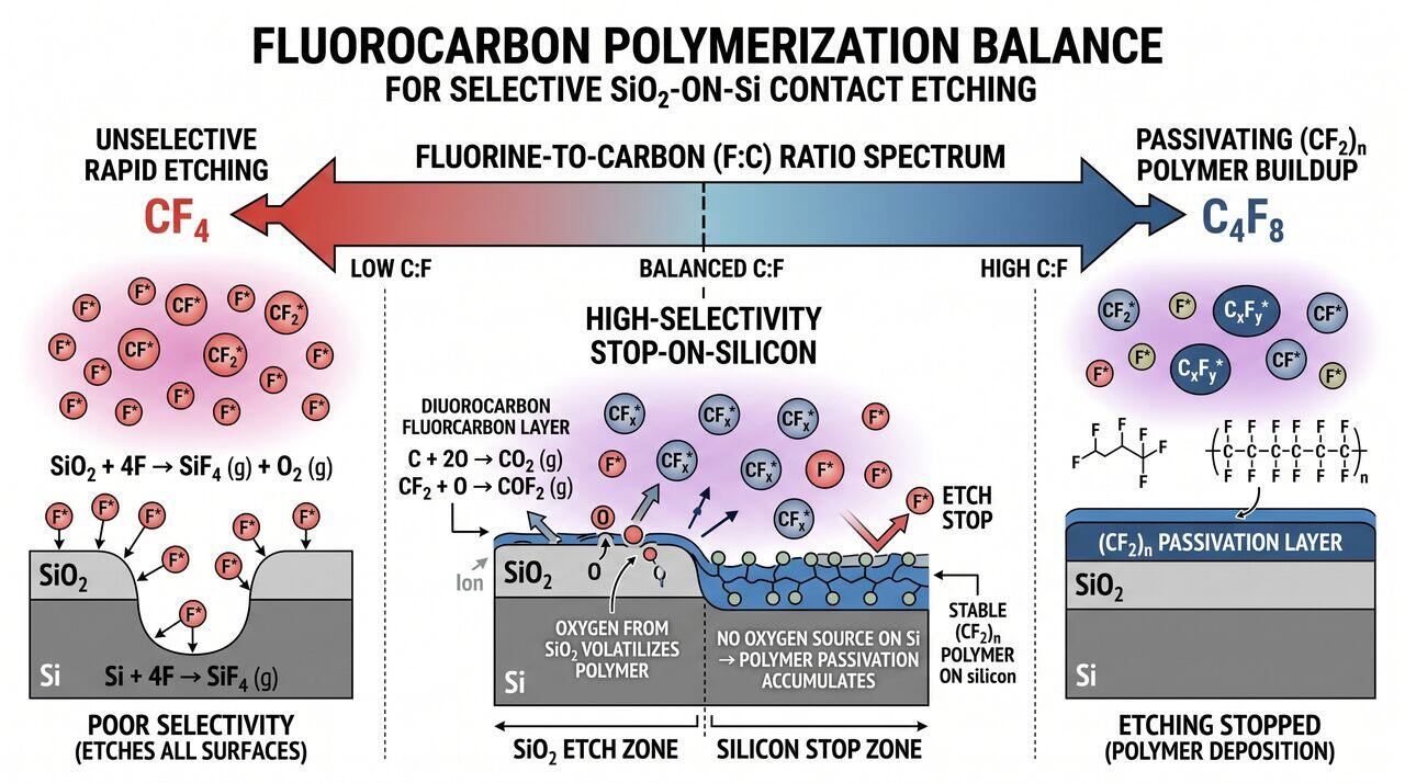
For oxide () etching over silicon (), fluorocarbon gas mixtures () rely on a dynamic balance between etching and polymer deposition:
- Radicals: Act as precursor species for polymer film formation.
- Selective Etching Mechanics: On surfaces, oxygen released from the oxide breaks down the fluorocarbon polymer film, allowing continuous etching. On underlying silicon (), no internal oxygen is present, allowing thick fluorocarbon polymer accumulation that halts etching, achieving high selectivity ().
→Prerequisites & continue reading
Prerequisites: ["p06-t6.1-t1-plasma-etching-rie-icp-ccp-fundamentals"]
Also in Topic 6.1, Reactive Ion Etching & Plasma Physics:
Tier 1 · Plasma Etching & Reactive Ion Etching (RIE): Core Fu…Tier 3 · Plasma Sheath Physics, Bohm Criterion & Sidewall Pas…