01Submerged Arc Furnace (SAF) Hardware Architecture
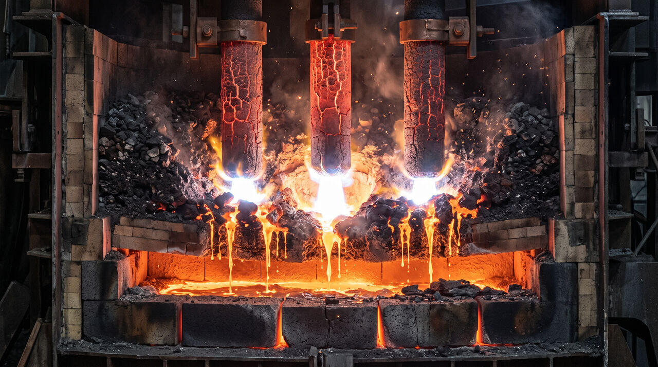
The industrial production of Metallurgical-Grade Silicon (MG-Si) is executed inside massive Submerged Arc Furnaces (SAF) rated between and of electrical power. Unlike open-arc steelmaking furnaces, the electric arcs in an SAF are deeply submerged beneath a permeable bed of solid raw materials known as the furnace charge (or burden).
Key Hardware Components
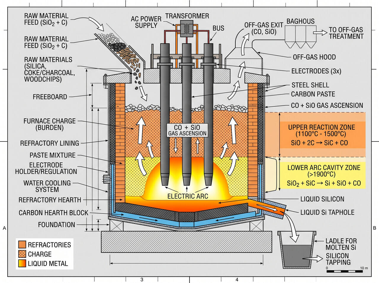
- Søderberg Self-Baking Electrodes: Three massive vertical carbon/graphite electrodes (up to in diameter) supplied with three-phase alternating current (AC).
- Refractory Hearth & Shell: A water-cooled cylindrical steel shell lined with high-density carbon blocks and silicon carbide () refractories at the bottom tap hole.
- Rotating Furnace Body: Many modern SAFs slowly rotate or oscillate () to break up crust formation and maintain uniform burden distribution.
02Multi-Zone Thermal Topology & Internal Gas Kinematics
The interior of a silicon SAF operates under a steep vertical temperature gradient divided into two primary reactive zones:
Zone 1: Upper Low-Temperature Zone ()
In the cooler upper region of the furnace shaft, descending solid carbon materials react with rising silicon monoxide gas () generated in the lower zone to form solid silicon carbide ():
This reaction is critical for furnace efficiency; it recycles volatile silicon gas before it can escape out the top exhaust, converting solid carbon into reactive .
Zone 2: Lower High-Temperature Zone ()
In the immediate vicinity of the electric arc plasma cavity, quartz melts and reacts with the newly formed silicon carbide to produce liquid elemental silicon:
03Operational Parameter Matrix & Process Control
Maintaining continuous, steady-state operation requires delicate balance across electrical, material, and thermal parameters:
| Operational Parameter | Nominal Control Range | Consequence of Out-of-Spec Operation |
|---|---|---|
| Operating Temperature | (Arc Cavity) | : Furnace freezes; : Excessive gas loss. |
| Charge Porosity & Size | Quartz: ; Woodchips: | Low porosity causes gas blowouts ("blowholes") and electrode tipping. |
| Fixed Carbon Ratio | of stoichiometric requirement | Under-coking leaves unreduced ; Over-coking forms excess crust. |
| Electrical Power Density | electrode surface | Improper arc positioning leads to shallow hearth heating or refractory damage. |
04Tapping and Refining Operations
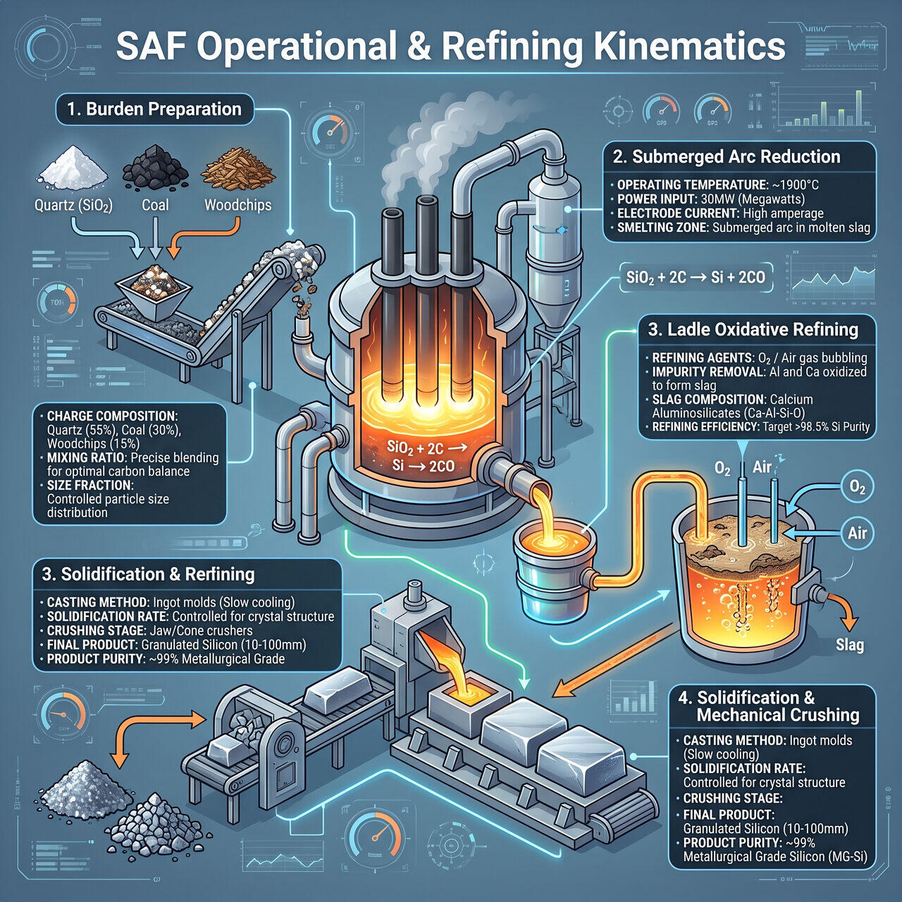
Liquid silicon collects at the bottom carbon hearth at approximately . At regular intervals (), the tap hole is drilled open.
- Oxidative Ladle Refining: Oxygen or air enriched with chlorine gas is bubbled through the molten liquid silicon in the ladle. Calcium () and aluminum () impurities oxidize preferentially before silicon, forming a floating slag layer () that is skimmed off.
- Casting & Crushing: The refined molten silicon is poured into shallow iron molds, cooled, and mechanically crushed into uniform granules () ready for chemical processing into trichlorosilane.
→Prerequisites & continue reading
Prerequisites: Understanding of carbothermic reduction fundamentals and industrial thermodynamics
Also in Topic 1.1, Quartzite Extraction & Carbothermic Reduction:
Tier 1 · From Sand to Silicon: The Journey of Quartzite Reduc…Tier 3 · Thermodynamics of Carbothermic Reduction and Impurit…