01Thermodynamic Phase Equilibria in the Si-O-C System
The carbothermic reduction of silica () is fundamentally constrained by the phase equilibria of the ternary Si-O-C system. Unlike simple metal reductions (such as iron smelting), silicon reduction cannot proceed directly from oxide to metal without passing through condensed intermediate compounds () and volatile gaseous phases ().
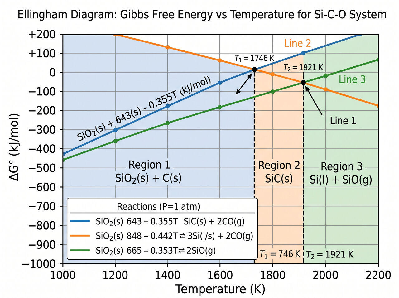
Free Energy Dependencies & Ellingham Analysis
The thermodynamic feasibility of reactions within the furnace shaft is governed by the standard Gibbs free energy change () as a function of temperature (T in Kelvin):
- Formation of Silicon Carbide ():
Equilibrium temperature ( where at ): .
- Primary Reduction to Liquid Silicon ():
Equilibrium temperature ( at ): .
- Volatile Silicon Monoxide Generation:
02Volatilization Dynamics and Silicon Yield Equations
The total silicon yield () of a submerged arc furnace is dictated by the fraction of silicon lost as volatile gas escaping through the top charge shaft.
The thermodynamic minimum partial pressure of gas inside the arc zone is defined by the equilibrium constant :
Where and represent the thermodynamic activities of liquid silica and liquid silicon, respectively. If the upper bed temperature drops below or lacks reactive carbon surface area, gas cannot react according to , resulting in massive silicon yield degradation. Overall silicon recovery is modeled by:
Modern high-efficiency furnaces achieve , with remaining losses manifesting as silica fume ( micro-dust) in the gas abatement baghouses.
03Impurity Partitioning Thermodynamics
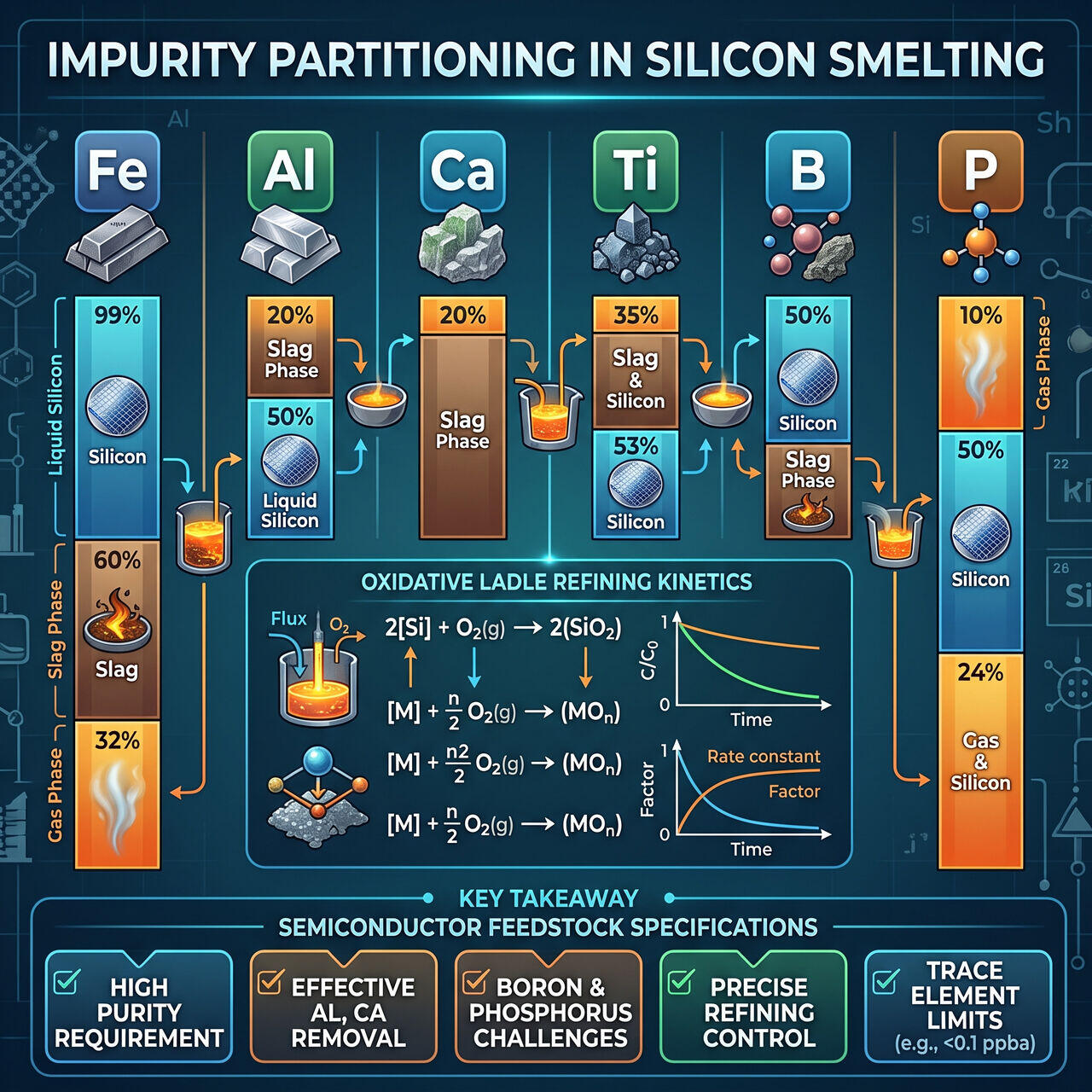
During carbothermic reduction, trace metallic and non-metallic elements present in quartzite and carbon reductants partition between the liquid silicon phase, slag phase, and off-gas stream.
Thermodynamics of Trace Impurity Elements:
| Impurity Element | Thermodynamic Behavior & Partition Coefficient () | Primary Source | Fate / Removal Strategy |
|---|---|---|---|
| Iron () | ; Nearly retains in liquid silicon. | Quartzite, Steel tools | Cannot be removed by ladle refining; requires chemical chlorination. |
| Aluminum () | ; High oxide affinity (). | Ash in coal, Clay minerals | Oxidized via ladle oxygen bubbling ( slag). |
| Calcium () | ; Volatile at arc temperatures. | Woodchips, Limestone | Oxidized via oxygen/chlorine gas bubbling into floating slag. |
| Titanium () | ; Forms stable titanium silicides (). | Heavy minerals in quartzite | Retained in liquid metal; requires chemical distillation downstream. |
| Boron () | ; Extremely stable in molten Si. | Coal ash | Extremely difficult to remove; strictly controlled at feedstock intake. |
| Phosphorus () | ; Highly volatile gas species. | Coal, Charcoal | Partially volatilizes; remainder retained in silicon matrix. |
04Mathematical Model of Ladle Slag Refining Kinematics
The oxidative removal rate of calcium and aluminum from liquid silicon in the refining ladle follows first-order mass-transfer-controlled kinetics:
Where:
- is the weight percentage of impurity metal ( or ) in molten silicon.
- is the overall mass transfer coefficient ().
- A/V is the interfacial reaction area per unit melt volume ().
- is the thermodynamic equilibrium concentration at the slag-metal interface.
By injecting gas fine bubbles () through bottom porous plugs, A/V is maximized, reducing and levels from down to in under 45 minutes.
→Prerequisites & continue reading
Prerequisites: Advanced thermodynamics (Ellingham diagrams, Gibbs free energy, phase equilibria)
Also in Topic 1.1, Quartzite Extraction & Carbothermic Reduction:
Tier 1 · From Sand to Silicon: The Journey of Quartzite Reduc…Tier 2 · Inside the Submerged Arc Furnace: Thermal & Electric…