01Fluidized Bed Hydrochlorination Tool Architecture
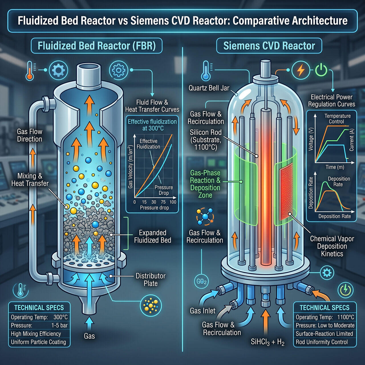
The initial chemical conversion of crude solid Metallurgical-Grade Silicon () into volatile trichlorosilane (, TCS) occurs in a high-pressure Fluidized Bed Reactor (FBR).
Fluidization Kinematics
- Gas Distribution Grid: Anhydrous gas is pumped upward through a perforated bottom grid plate at velocities exceeding the minimum fluidization velocity ().
- Bed Behavior: Solid particles () become suspended in the upward gas stream, behaving like a bubbling liquid. This maximizes gas-solid contact area and maintains uniform thermal distribution ( at ).
- Exothermic Heat Extraction: The hydrochlorination reaction () is strongly exothermic (). Internal cooling coils circulate heat-transfer fluids to prevent thermal runaway above , which favors unwanted silicon tetrachloride (, STC) formation.
02Multi-Stage Distillation Train Hardware
To achieve the parts-per-trillion purity needed for 11N EGS, crude TCS liquid passes through a distillation train consisting of high-efficiency tray or packed columns operating under closed-loop nitrogen pressure:
Column Component Engineering
- High-Theoretical-Plate Columns: Distillation towers utilize structured stainless steel packing (providing 50-100 theoretical plates per column) to separate chlorosilane species with close boiling points ( at vs at ).
- Complexation Additives: To remove boron impurities (, boiling point ) whose volatility overlaps with TCS, Lewis base complexing agents (such as benzaldehyde or triphenylchloromethane) are injected. These agents bind selectively to , forming non-volatile adducts that drop to the column reboiler.
03Siemens CVD Bell Jar Reactor Mechanics
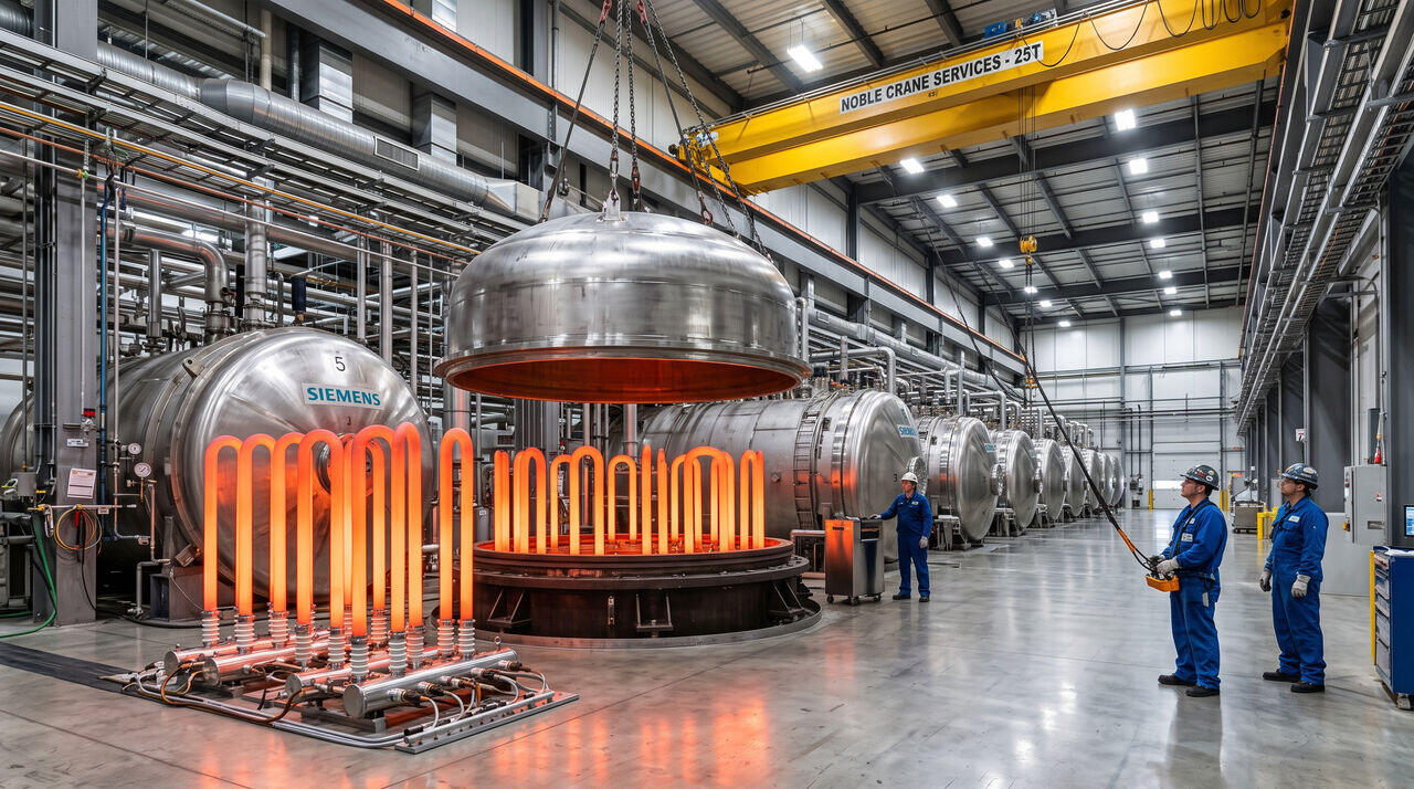
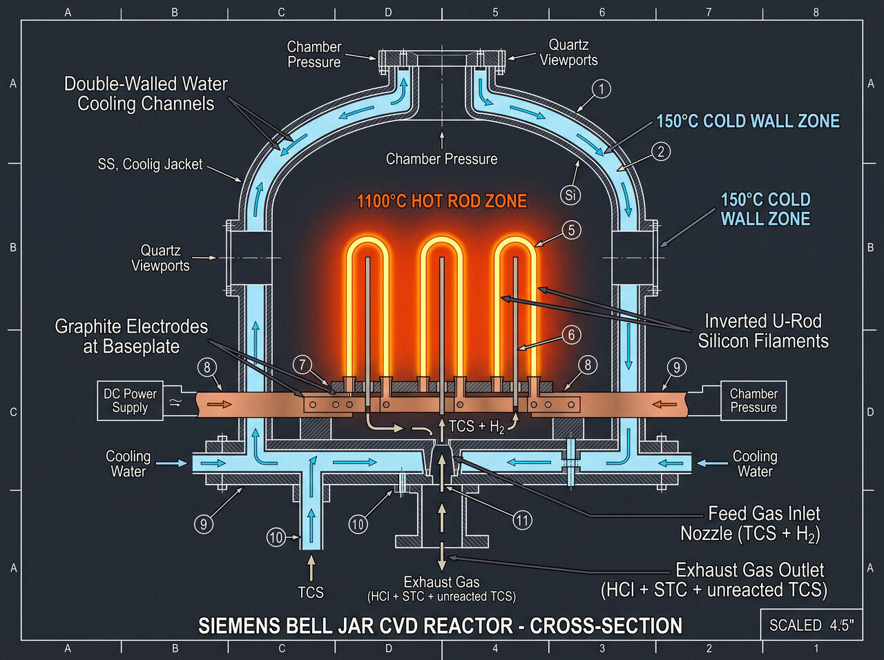
The heart of EGS production is the Siemens Bell Jar CVD Reactor, a high-current, water-cooled pressure vessel.
Key Mechanical Subsystems
- Double-Walled Silver/Steel Bell Jar: A water-cooled outer dome keeps wall temperatures below , preventing gas-phase nucleation and undesirable silicon deposition on wall surfaces.
- Filament Power Control: Thin silicon seed filaments ( diameter, high) are arranged in inverted U-configurations. Direct AC Joule heating drives filament temperatures to .
- Power Scaling Electronics: As rod diameters expand from to , electrical resistance drops dramatically. High-power transformer arrays automatically adjust voltage (downward) and current (upward, reaching several thousand amperes per bridge) to maintain a constant surface temperature.
04Equipment Parameter Comparison Matrix
| Operational Parameter | Fluidized Bed Hydrochlorinator | Siemens CVD Bell Jar Reactor |
|---|---|---|
| Operating Temperature | (Rod Surface) | |
| Operating Pressure | ||
| Primary Chemical Inflow | powder + Anhydrous gas | Purified vapor + gas |
| Primary Output | Crude liquid TCS () | Solid High-Purity EGS Polysilicon Rods |
| Energy Consumption | Low () | High () |
→Prerequisites & continue reading
Prerequisites: Understanding of TCS synthesis and Siemens process fundamentals
Also in Topic 1.2, Chemical Purification & the Siemens Process:
Tier 1 · Achieving 11N Purity: Trichlorosilane and the Siemen…Tier 3 · CVD Deposition Kinetics and Mass-Transfer Dynamics i…