01Gas-Phase Thermodynamics and Reaction Pathways
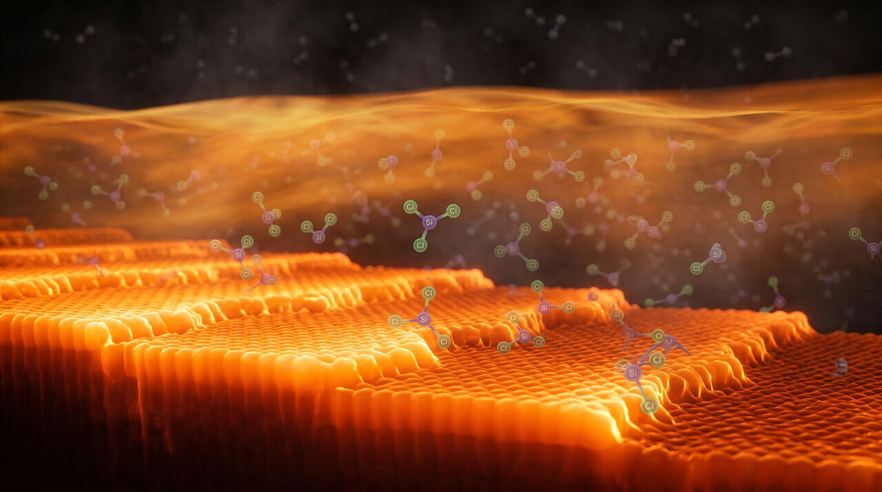
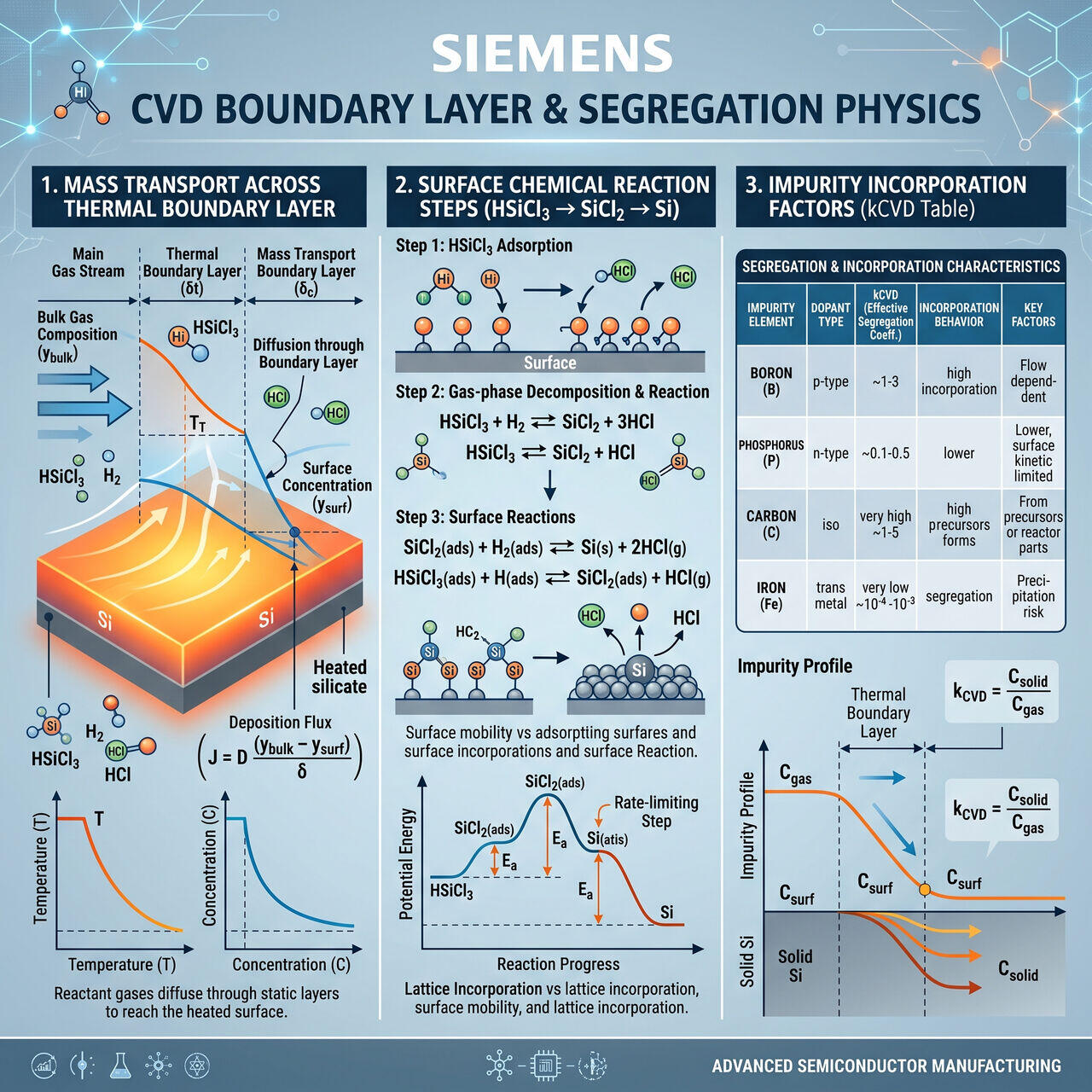
The deposition of silicon from trichlorosilane (, TCS) in a Siemens CVD reactor involves a coupled network of homogeneous gas-phase reactions and heterogeneous surface reactions.
Primary Reaction Mechanisms
- Homogeneous Pyrolysis in Gas Phase:
Dichlorosilylene () is the primary reactive intermediate generated in the gas phase adjacent to the hot rod surface.
- Heterogeneous Reduction at Rod Surface:
- Competing Etch Back Reaction (Hydrogen Chloride Attack):
At high temperatures () or elevated partial pressures, the reverse etch reaction accelerates, consuming deposited silicon and lowering net growth rates.
02Boundary Layer Mass Transfer and Growth Rate Equations
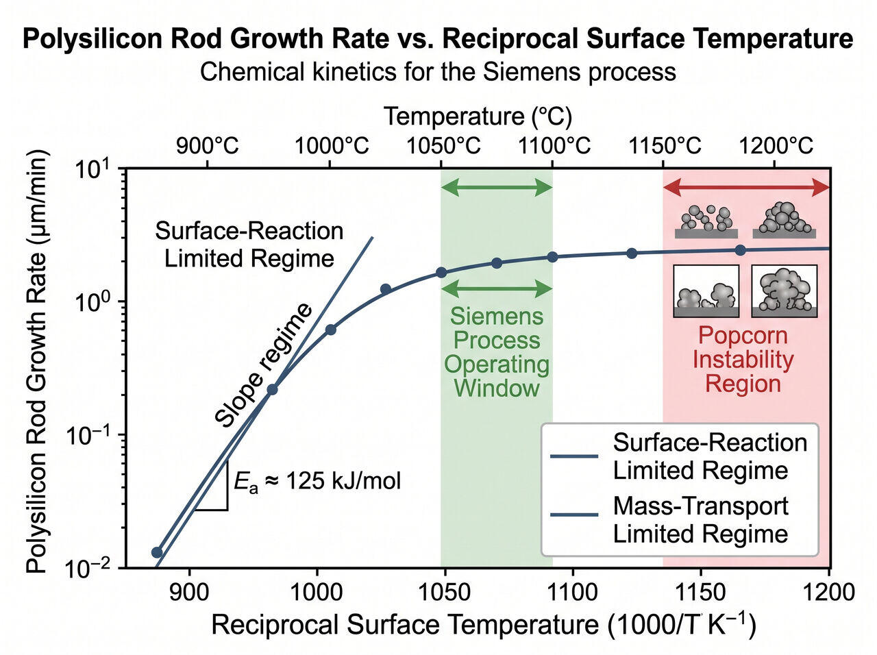
The linear growth rate (G, in ) of the polysilicon rod is governed by the interplay between surface reaction kinetics () and boundary layer mass transport ().
The overall deposition flux (, in ) is expressed by:
Where:
- is the concentration of TCS in the bulk gas flow.
- is the thermodynamic equilibrium concentration at the rod surface.
- is the mass transfer coefficient ( is binary diffusivity, is boundary layer thickness).
- is the surface reaction rate constant ().
Temperature Regime Operating Windows
- Surface-Reaction Limited (): Growth rate is strongly exponentially dependent on temperature. Yield is low, but surface morphology is exceptionally smooth and uniform.
- Mass-Transport Limited (): Growth is constrained by species diffusion across the stagnant boundary layer. Unstable dendrite/popcorn morphology forms due to gas-phase nucleation.
- Optimal Siemens Operating Window (): Operates in a balanced transition regime, maximizing growth rate () while maintaining high rod density and structural integrity.
03Impurity Segregation Thermodynamics in CVD Deposition
Although TCS feedstock is purified to 11N standards, trace levels of phosphorus (), boron (), arsenic (), and carbon () remain in the gas feed. The degree to which an impurity incorporates into the growing silicon lattice during CVD is dictated by its gas-to-solid segregation coefficient ():
| Impurity Species | Segregation Factor | Incorporation Mechanism | Control Strategy |
|---|---|---|---|
| Boron () | Incorporates readily via . | High-efficiency pre-complexation in distillation. | |
| Phosphorus () | Lower incorporation efficiency due to stable volatile . | Managed via high-boiling column bottoms removal. | |
| Carbon () | Incorporates via organochlorosilanes (). | Controlled by strict removal of organic species in distillation. | |
| Heavy Metals () | Non-volatile chlorides (); near-zero incorporation at . | Silane gas feed lines constructed of polished electro-purified alloy. |
04Morphological Stability and Popcorn Prevention
A major failure mode in Siemens reactors is popcorn growth: a severe surface roughening condition where dendritic silicon nodules sprout from the rod surface.
Prevention Metrics
Popcorn growth occurs when homogenous gas-phase nucleation produces silicon dust clusters that land on the rod. To suppress popcorn defectivity:
- Maintain molar feed ratio .
- Limit thermal boundary layer supersaturation by optimizing gas inlet nozzle velocity ().
- Precisely stabilize rod surface temperature at via adaptive pyrometer control.
→Prerequisites & continue reading
Prerequisites: Advanced chemical thermodynamics, boundary layer mass transfer, CVD surface physics
Also in Topic 1.2, Chemical Purification & the Siemens Process:
Tier 1 · Achieving 11N Purity: Trichlorosilane and the Siemen…Tier 2 · Fractional Distillation Columns and Siemens CVD Reac…