01Tool Architecture of Double-Side Planetary Lapping Machines
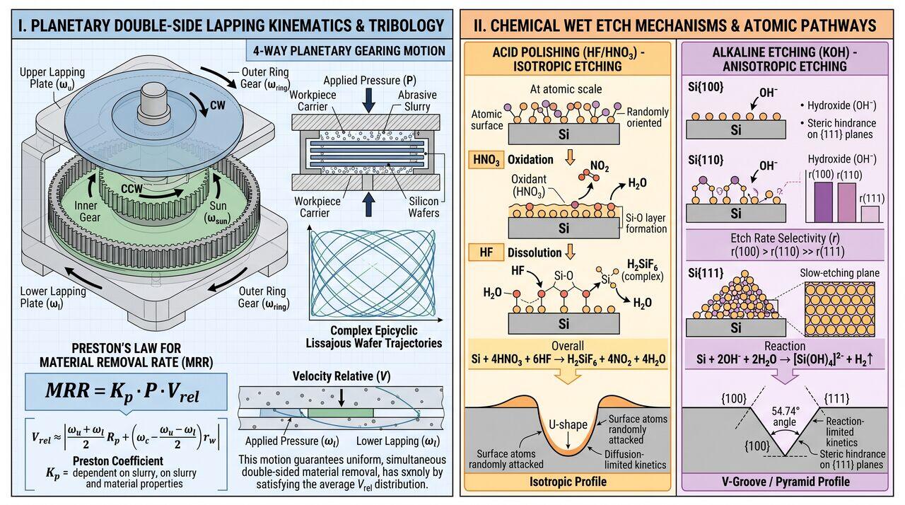
Industrial Double-Side Lappers (DSL) are heavy 4-way planetary gear machining systems engineered to lap up to 30 large wafers simultaneously under high downward pressure ().
The 4-Way Independent Drive Motion
A planetary lapping machine controls four independent rotational velocity axes:
- Lower Lapping Plate Rotational Velocity (): Clockwise rotation of the bottom cast-iron plate.
- Upper Lapping Plate Rotational Velocity (): Counter-clockwise rotation of the top cast-iron plate.
- Inner Sun Gear Rotational Velocity (): Central driving gear imparting epicyclic rotation to the carrier disks.
- Outer Ring Gear Rotational Velocity (): Outer internal gear mesh guiding the orbital path of carrier disks.
By precisely tuning the speed ratios , every point on every wafer describes a complex, non-repeating Lissajous trajectory across the lapping plate surface, ensuring perfectly uniform plate wear and sub-micrometer wafer parallelism ().
02Planetary Lapping Kinematics & Prestonian Material Removal Modeling
Material removal rate (MRR) during double-side lapping is governed by Preston's Law:
Where:
- h = Total silicon thickness removed ().
- = Preston coefficient (), encapsulating slurry abrasive hardness, grain size distribution, and fluid viscosity.
- P = Downward pneumatic plate pressure ().
- = Relative sliding velocity between wafer surface and lapping plate ().
Mathematical Relative Velocity Distribution
The relative velocity at any point on a wafer positioned at orbital radius inside a carrier is given by vector summation of plate and orbital motions:
To prevent the lapping plates from wearing into concave or convex parabolic shapes over time (which degrades wafer flatness), the controller dynamically adjusts the speed ratio to maintain a mathematically uniform time-integrated relative velocity distribution across the entire plate radius.
03Lapping Slurry Tribology & Abrasive Grain Dynamics
Lapping operates in the three-body abrasive wear regime, where hard abrasive grains roll and slide within a liquid film gap between the cast-iron plate and the silicon wafer.
Abrasive Material Selection & Grain Size Progression
- Micro-Indentation Rolling Action: As cast-iron plates compress slurry grains ( alumina or micro-diamond) against silicon, high localized contact stresses induce micro-fractures, chipping away microscopic silicon fragments.
- Plate Conditioning & Grooving: Lapping plates feature radial and concentric spiral grooves to distribute slurry evenly across the plate face and flush abraded silicon swarf away from carrier pockets.
04Chemical Stress-Relief Etching Tool Mechanics & Bath Chemistry
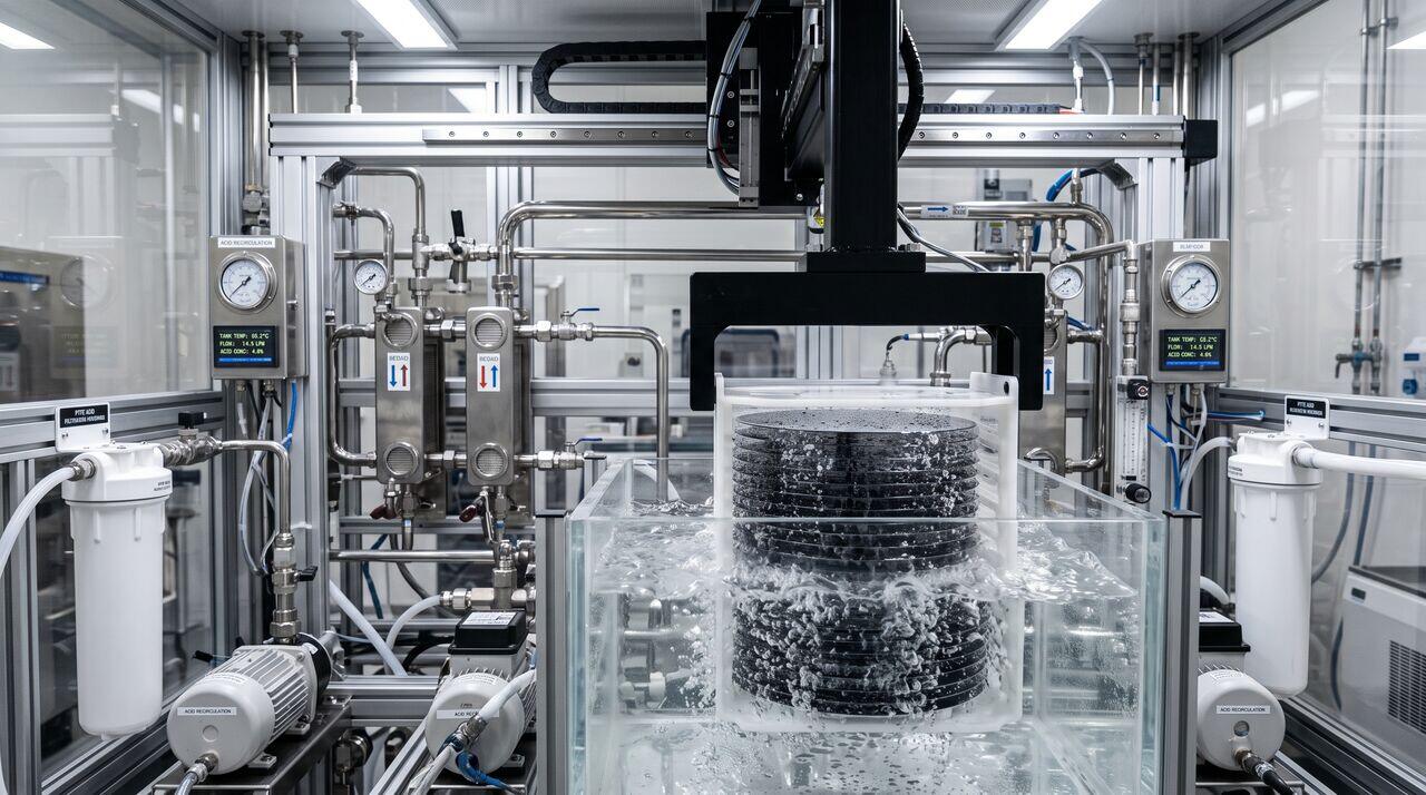
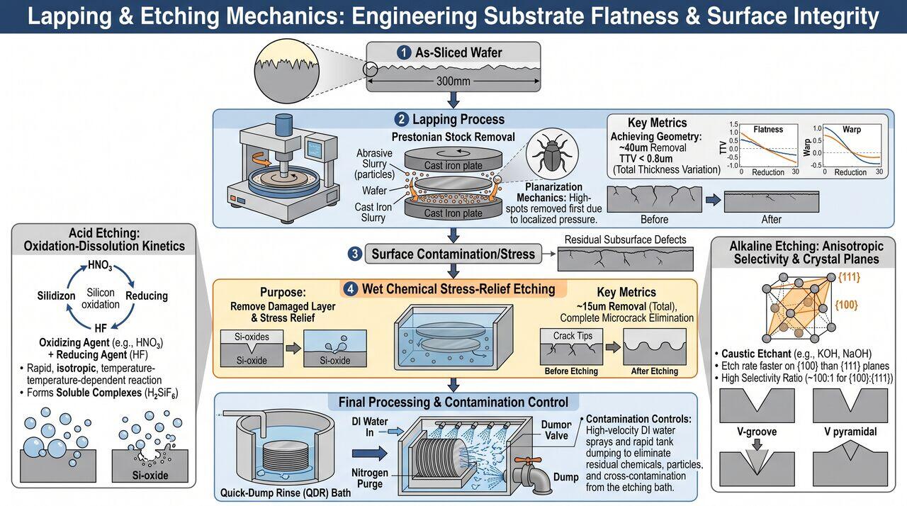
Following double-side lapping, wafers are transferred to automated wet etching benches to chemically dissolve the lapping-induced subsurface damage layer.
Acid Etching Kinetics ()
Acid etching operates via a two-step oxidation-dissolution reaction:
- Oxidation by Nitric Acid:
- Dissolution by Hydrofluoric Acid:
- Overall Reaction:
- Rate Limiting Step: Diffusion of species to the wafer surface. High concentration yields rapid, diffusion-controlled isotropic polishing that rounds surface micro-roughness.
Alkaline Etching Kinetics ()
Alkaline etching involves direct nucleophilic attack by hydroxide ions ():
- Anisotropic Selectivity: Reaction rates vary dramatically by crystallographic plane: Etch Rate . Etch rate on planes is slower than on planes due to atomic packing density!
05Process Parameter Comparison Matrix
| Operational Parameter | Planetary Lapping | Acid Wet Etching | Alkaline Wet Etching |
|---|---|---|---|
| Primary Objective | Global thickness flattening (TTV) | Isotropic damage removal | Anisotropic stress relief |
| Target Stock Removal | total (/side) | total | total |
| Removal Uniformity | Within-Wafer Non-Uniformity | Sensitive to crystal orientation | |
| Surface Finish () | (Matte finish) | ("Orange peel") | (Pyramidal) |
| Residual Damage Depth | SSD | Zero SSD (Prisintine crystal) | Zero SSD (Pristine crystal) |
→Prerequisites & continue reading
Prerequisites: Wafer Edge Profiling, Lapping, and Stress-Relief Etching Fundamentals (Tier 1)
Also in Topic 2.3, Edge Profiling, Lapping & Stress-Relief Etching:
Tier 1 · Wafer Edge Profiling, Lapping, and Stress-Relief Etc…Tier 3 · Physics of Lapping & Etching: Tribochemistry, Anisot…