01Tool Architecture of Modern CNC Ingot Conditioning Systems
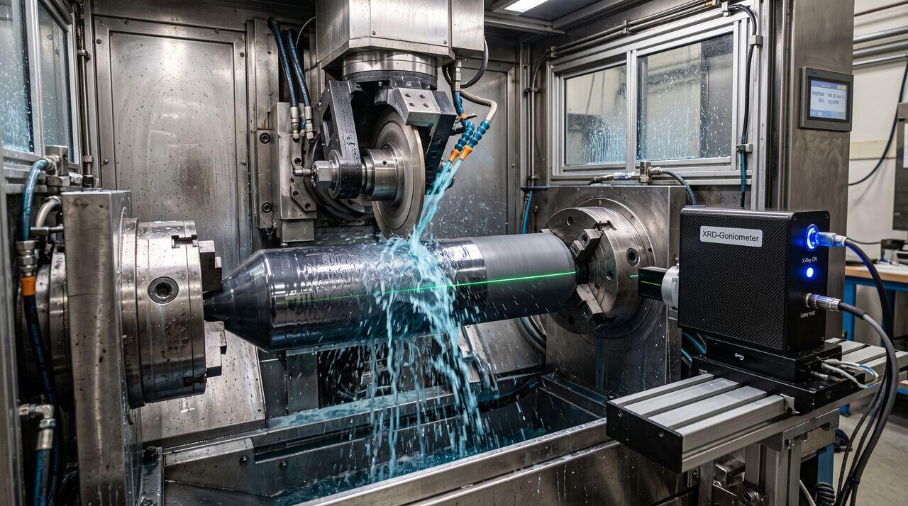
Industrial ingot conditioning equipment must process heavy single-crystal silicon blocks weighing up to and lengths exceeding with sub-micrometer mechanical repeatability. Modern heavy-duty CNC conditioning platforms integrate three core subsystems into a single automated cell:
Key Subsystem Components
- Dual Synchronization Spindle Headstocks: Heavy hydrostatic or magnetic bearing spindles chuck both ends of the cropped ingot using vacuum pads or specialized clamping fixtures. Both spindles rotate in perfect electronic synchronization to eliminate torsional twist along the crystal length.
- High-Stiffness Grinding Wheel Carriage: Driven by linear motor drives on ultra-rigid granite beds, carrying high-speed motorized grinding spindles operating at .
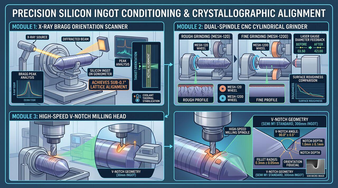
- X-Ray Crystal Orientation Head: Integrated X-ray tube and scintillation detector goniometer mounted directly on the tool bed for in-situ lattice orientation alignment prior to notch grinding.
- Closed-Loop Coolant Delivery & Filtration: High-flow synthetic coolant nozzles delivering temperature-stabilized () fluid at to flush silicon swarf and prevent thermal expansion errors.
02Ingot Orientation Kinematics & X-Ray Bragg Diffraction
Before grinding orientation flats or notches, the exact crystallographic axes (<100>, <110>, or <111>) of the crystal ingot must be located. While Czochralski growth attempts to follow a seed crystal orientation, small seed misalignment or thermal drift causes the true crystal axes to deviate by from the mechanical axis of the ingot.
X-Ray Bragg / Laue Diffraction Measurement
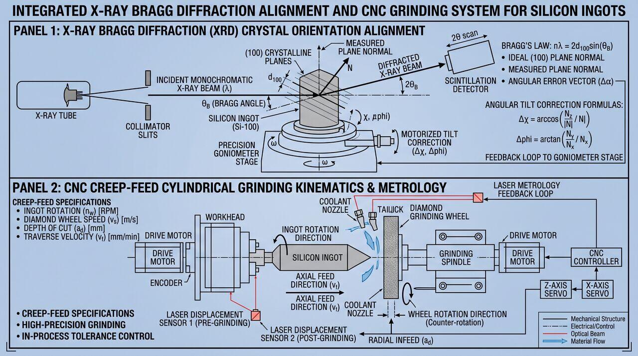
The tool uses X-ray diffraction based on Bragg's Law:
Where:
- = Wavelength of the characteristic X-ray beam ().
- = Interplanar spacing of the specific crystal planes (hkl) (e.g., for silicon).
- = Bragg diffraction angle.
Closed-Loop Orientation Measurement Sequence
- Primary Alignment Scanning: The X-ray source illuminates the cropped face or side of the ingot while the goniometer tilts the X-ray head through a small angular arc.
- Bragg Peak Detection: Scintillation detectors record the precise angular location () where diffracted intensity reaches its absolute maximum.
- Spatial Deviation Calculation: The CNC controller calculates the angular error vector between the physical spindle center line and the true crystallographic axis.
- Correction Alignment: The dual hydrostatic headstocks adjust their angular offset, aligning the true <100> or <110> lattice vector perfectly with the tool's milling trajectory before notch cutting begins.
03CNC Cylindrical Grinding Kinematics & Material Removal Rate
Outer diameter grinding operates on the principle of creep-feed cylindrical traverse grinding. The ingot rotates at a low rotational speed (), while the high-speed diamond wheel rotates at and traverses linearly along the longitudinal Z-axis of the ingot.
Mathematical Kinematics & Material Removal Rate (MRR)
The volumetric Material Removal Rate (MRR) during cylindrical grinding is governed by:
Where:
- = Ingot outer diameter ().
- = Radial depth of cut / plunge feed per pass ().
- = Axis traverse velocity ().
Operational Parameter Profiles
| Process Phase | Wheel Speed () | Ingot Speed () | Depth of Cut () | Traverse Speed () | Diamond Grit Size |
|---|---|---|---|---|---|
| Rough Grinding | Mesh 120 / 170 () | ||||
| Medium Finish | Mesh 325 / 400 () | ||||
| Spark-Out / Fine | (Dwell) | Mesh 800 / 1200 () |
Spark-out passes are dwell cycles performed with zero plunging depth () to smooth out mechanical deflections of the ingot and spindle under grinding forces, achieving ultra-high roundness ().
04Precision Notch and Primary Flat Milling Mechanics
Once cylindrical grinding achieves target outer diameter, the orientation notch or flat is precision milled without unclamping the ingot, preserving crystallographic reference coordinates.
Notch Milling Mechanics
- Tooling: Small resinoid or electroplated diamond form wheels operating at .
- Notch Geometry Control: For silicon wafers, SEMI M1 standards dictate a V-shaped notch with a corner fillet radius () and total depth of .
- Stress Minimization: The notch apex represents a geometric stress concentration point. Tooling path trajectories utilize smooth arc-in/arc-out plunge paths to avoid micro-chipping at the notch root, which could trigger wafer fracture during high-temperature fab annealing.
05Metrology Integration & Coolant Chemistry Management
In-Situ Metrology Verification
Modern conditioning tools incorporate non-contact optical laser gauge heads that sweep the ingot length in real time:
- Laser Triangulation Sensors: Measure outer diameter at 1,000 points per rotation across 100 axial positions to construct a 3D digital twin of the ingot geometry.
- Closed-Loop Feedback: If laser metrology detects mid-ingot thermal expansion bulge or taper, the CNC controller dynamically adjusts axis depth of cut () on subsequent fine passes.
Coolant Filtration & Thermal Stability
Silicon grinding produces ultra-fine elemental silicon slurry swarf ( particle size).
- Coolant Chemistry: Fully synthetic water-soluble fluids containing corrosion inhibitors, anti-foaming agents, and lubricating surfactants.
- Filtration: Continuous centrifugal separators and depth cartridge filters maintain swarf concentration below to prevent abrasive re-scratching and wheel loading.
→Prerequisites & continue reading
Prerequisites: Ingot Conditioning Fundamentals (Tier 1)
Also in Topic 2.1, Ingot Mechanical Processing & Geometric Conditioning:
Tier 1 · Ingot Conditioning Fundamentals: Cropping, Cylindric…Tier 3 · Physics of Ingot Grinding: Brittle-to-Ductile Transi…