01Introduction & Physical Purpose
When a single-crystal silicon ingot emerges from a Czochralski (CZ) crystal puller, it is far from ready for slicing into wafers. The as-grown ingot resembles a rough, heavy, dark-gray cylinder tapering at both ends, a conical "seed neck" at the top and a pointed "tail cone" at the bottom. Furthermore, its diameter fluctuates along its length due to minor thermal and mechanical variations during growth, and its outer surface is covered with irregular surface ripple marks and thermal oxide skin.
Ingot conditioning is the foundational mechanical preparation phase that converts a raw, irregularly shaped silicon single crystal into a perfectly cylindrical, dimensionally precise, and crystallographically oriented rod ready for precision slicing.
Without ingot conditioning:
- Slicing tools would fail: Diameter variations would cause severe mechanical instabilities and uneven wire tensions during wire sawing.
- Lithography tools could not align wafers: Photolithography scanners require an exact mechanical reference (a notch or flat) to know the precise crystallographic axes (e.g.,
<100>or<111>) of the crystal lattice. - Automated robotic handling would break: Modern fab automated material handling systems (AMHS) and cassette transfer tools demand absolute outer diameter tolerances within .
02The Three Sequential Conditioning Steps
Ingot conditioning consists of three distinct mechanical shaping operations:
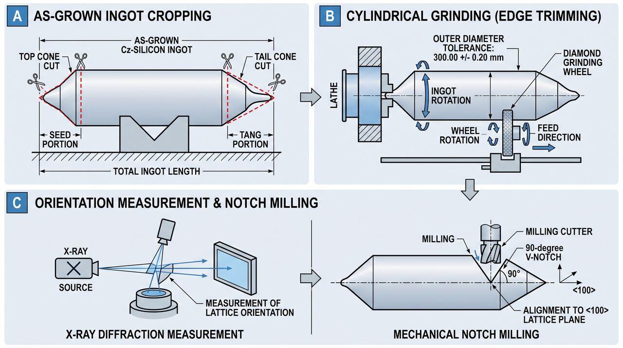
Step 1: Ingot Cropping (Cropping Saw)
- What it does: Uses a high-speed diamond band saw or inner-diameter (ID) diamond saw to cut off the top cone (seed end) and bottom cone (tail end) of the ingot.
- Why it matters: The top and bottom cones contain high concentrations of structural crystal defects (dislocations) and non-uniform thermal stress history. Cutting these off leaves a flat-ended cylinder containing only pristine single-crystal silicon.
- Cropping Inspection: The cropped faces are immediately chemically etched and inspected under infrared or X-ray inspection tools to verify that the crystal structure remains dislocation-free throughout the entire rod length.
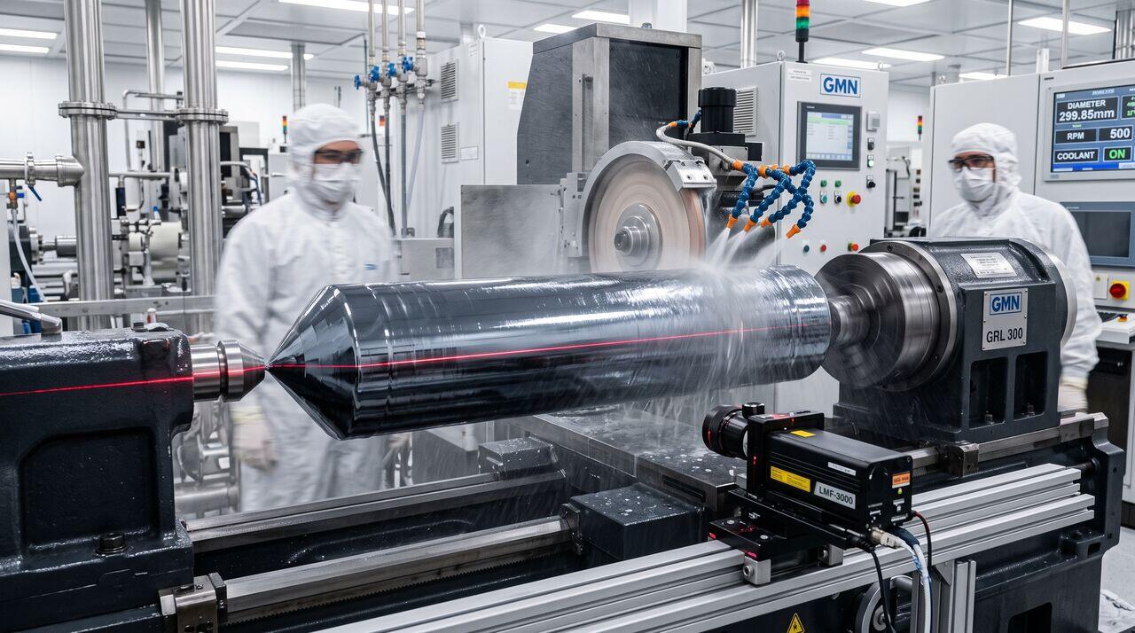
Step 2: Outer Diameter (OD) Cylindrical Grinding
- What it does: The cropped ingot is mounted on a heavy-duty CNC cylindrical grinding lathe. A rotating diamond-impregnated grinding wheel grinds away the outer surface until the ingot reaches an exact target diameter.
- Standard Diameters:
- 200 mm Wafers: Ground to exactly .
- 300 mm Wafers: Ground to exactly .
- Why it matters: CZ crystals are grown slightly oversized (e.g., for a target) to ensure that after grinding away surface roughness and microcracks, the final rod has a pristine, perfectly round cross-section.
Step 3: Orientation Notch or Flat Formation
To process wafers in fab tools, every wafer must indicate its internal crystal lattice orientation.
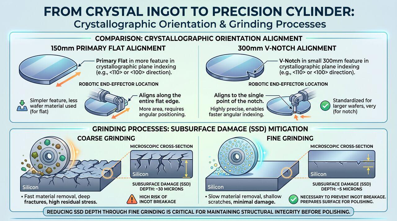
- Primary Flat (100 mm and 150 mm Wafers): A long, flat edge ground along the entire side of the ingot cylinder.
- Orientation Notch (200 mm and 300 mm Wafers): A small, precisely milled V-shaped notch ground into the side of the cylinder.
03Key Process Parameters & Quality Standards
| Parameter | 200 mm Wafer Spec | 300 mm Wafer Spec | Purpose / Impact |
|---|---|---|---|
| Target Outer Diameter | Ensures precise fit in fab chucks and cassettes | ||
| Cylindricity / Taper | over 1m | over 1m | Prevents wire alignment errors during slicing |
| Orientation Alignment | to crystallographic plane | to crystallographic plane | Aligns chip layout with Si atomic cleavage planes |
| Notch Depth | N/A (Uses Primary Flat) | Mechanical alignment key for fab robots | |
| Notch Angle | N/A | Optical sensor detection alignment |
04Mechanical Damage vs. Surface Quality Trade-Off
Grinding silicon is inherently an abrasive mechanical material removal process. Because single-crystal silicon is extremely hard and brittle, diamond grinding wheels produce Subsurface Damage (SSD): a network of microscopic cracks and lattice dislocation stresses extending tens of micrometers below the freshly ground surface.
- Coarse Grinding: Removes material rapidly () but leaves deep subsurface damage ().
- Fine Grinding: Uses smaller diamond grit sizes to gently remove the coarse damage layer, reducing final SSD to .
If subsurface damage is not properly controlled during cylindrical grinding, deep cracks can propagate inward during subsequent thermal processing, causing catastrophic wafer fracture inside high-temperature diffusion furnaces!
05Summary & Next Steps in the Fab
Ingot conditioning transforms an irregular, as-grown crystal ingot into a perfectly dimensioned cylindrical rod featuring:
- Flat, defect-inspected cropped ends.
- Absolute outer diameter uniformity ().
- A crystallographically aligned reference notch.
With conditioning complete, the silicon cylinder is ready for the next major mechanical milestone: Multi-Wire Diamond Sawing, where the block is sliced into thousands of ultra-thin silicon wafers.
→Prerequisites & continue reading
Prerequisites: Understanding of Single-Crystal Silicon Ingot Growth (Czochralski/Float-Zone)
Also in Topic 2.1, Ingot Mechanical Processing & Geometric Conditioning:
Tier 2 · Ingot Conditioning Kinematics: CNC Cylindrical Grind…Tier 3 · Physics of Ingot Grinding: Brittle-to-Ductile Transi…