01Executive Summary & Fundamental Material Behavior
Single-crystal silicon is a covalent diamond-cubic solid characterized by high hardness () and low fracture toughness (). When diamond abrasive grains engage the surface of a single-crystal silicon ingot during cylindrical grinding, the material response ranges from elastic deformation and high-pressure phase transformation (ductile regime) to micro-cleavage fracture and propagation of subsurface damage (brittle regime).
Understanding the fundamental mechanics of Subsurface Damage (SSD) formation during ingot conditioning is critical to fab yield. Deep microcracks generated during outer diameter grinding act as stress intensity concentrators (). If unmitigated, these cracks survive subsequent wafering and CMP processes, ultimately causing catastrophic wafer shatter under thermal shock during high-temperature thermal oxidation or rapid thermal annealing (RTA).
02Indentation Fracture Mechanics & Crack Propagation Models
The interaction between a single diamond abrasive grain and the silicon lattice is modeled using sharp indenter fracture mechanics (Lawn, Evans, and Marshall model).
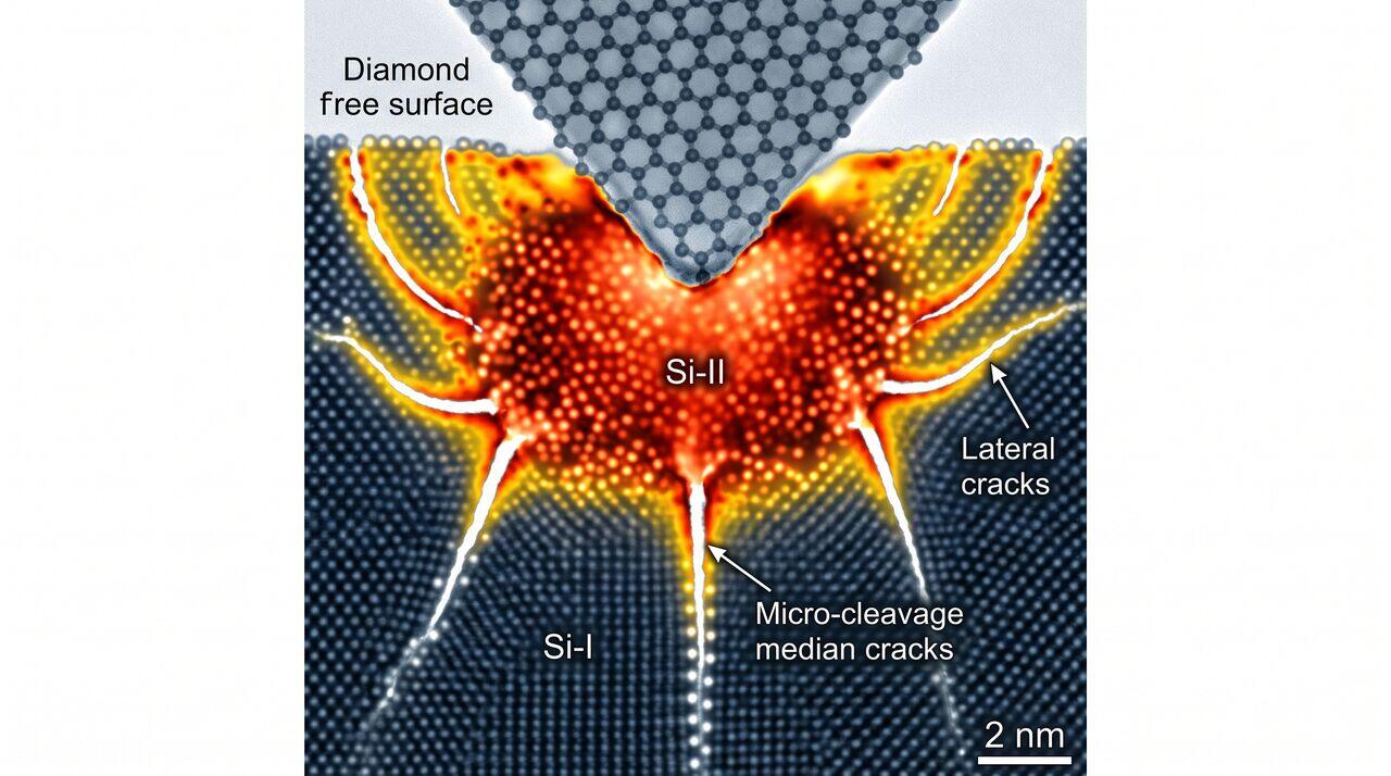
As a diamond grain plunges into the silicon substrate under normal grinding force , a localized hydrostatic stress field develops directly beneath the abrasive tip. When hydrostatic pressure exceeds , silicon undergoes a solid-state phase transformation from covalent crystalline diamond-cubic (Si-I) to metallic metallic metallic-beta-tin phase (Si-II).
Crack System Nucleation
- Plastic / Phase-Transformed Core: Immediately surrounding the diamond grain contact zone.
- Median Cracks: As normal force increases, vertical median cracks nucleate at the elastic-plastic boundary and propagate downward into the bulk substrate parallel to the loading axis. Median cracks define the maximum depth of Subsurface Damage ().
- Radial Cracks: Surface-breaching cracks radiating outward from the contact site.
- Lateral Cracks: During grain unloading, elastic rebound of the surrounding bulk matrix creates severe tensile stresses that spawn lateral cracks growing parallel to the surface. When lateral cracks intersect the surface, material chippage (spalling) occurs, dictating surface roughness ().
Mathematical SSD Depth Prediction Model
The maximum depth of median cracking (), and thus the maximum Subsurface Damage depth (), scales with normal force per diamond grit (), material hardness (H), fracture toughness (), and Young's modulus (E):
Where:
- = Dimensionless indenter geometry calibration constant ().
- E = Young's Modulus of Silicon ( for , for ).
- H = Hardness of Silicon ().
- = Mode-I Fracture Toughness ( for cleavage planes).
- = Experimental exponent ().
03The Brittle-to-Ductile Grinding Transition
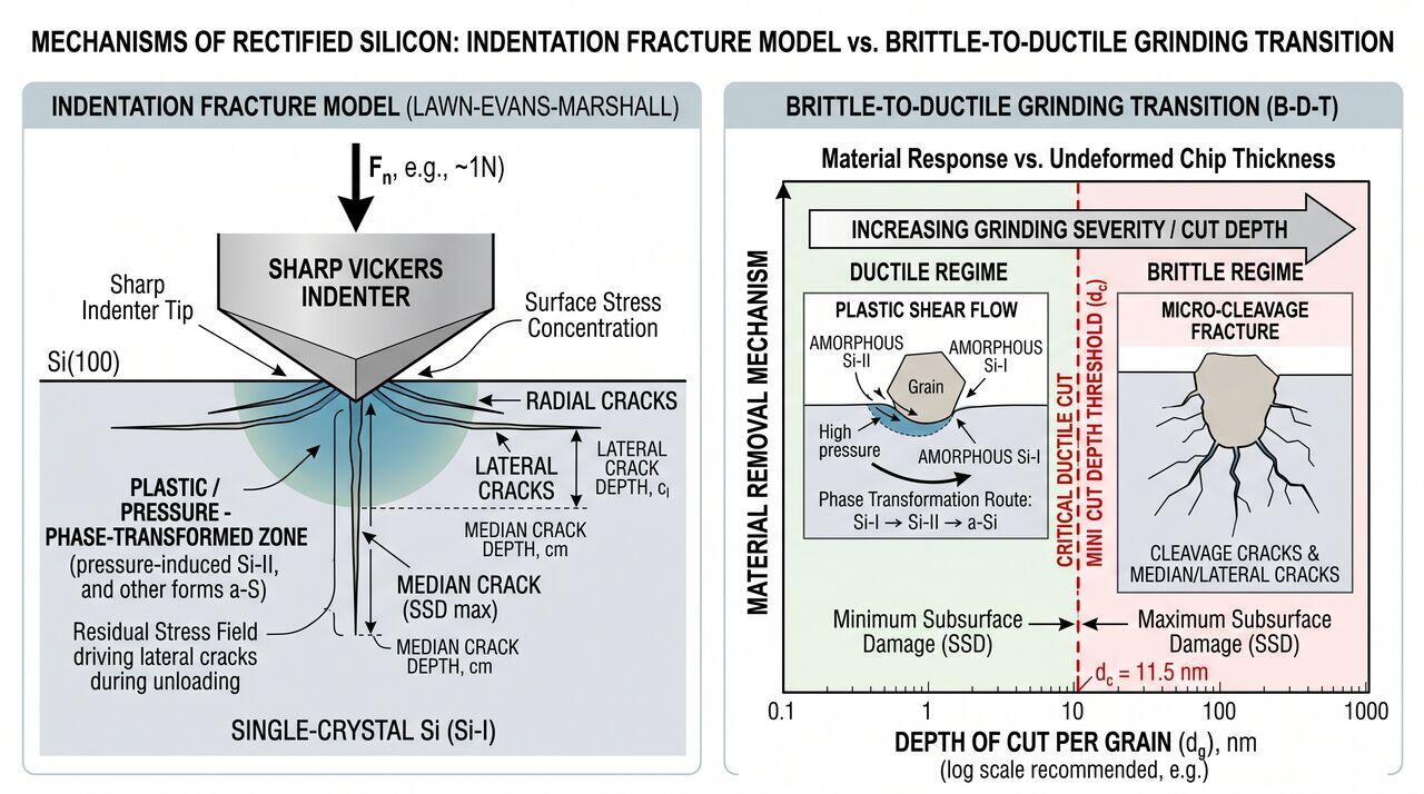
While silicon is nominally brittle, material removal can occur entirely via ductile plastic flow without crack nucleation if the depth of cut per abrasive grain () remains below a critical threshold known as the Critical Ductile Cut Depth ().
Critical Depth Formula (Bifano Model)
The critical cut depth for the brittle-to-ductile transition is given by:
Where is a material-independent constant ().
Quantitative Calculation for Silicon:
Substituting silicon's mechanical properties (, , ):
Industrial Engineering Consequence: In commercial cylindrical grinding tools, achieving across the entire ingot is impractical for roughing passes due to throughput constraints. Therefore, rough grinding operates deliberately in the brittle regime (), followed by a multi-stage fine grinding sequence operating close to or within the ductile regime to extinguish deep median cracks.
04Phase Transformation Dynamics Under High-Pressure Contact
Raman spectroscopy of freshly ground silicon surfaces reveals that plastic deformation in the ductile regime is not caused by conventional dislocation glide, but by stress-induced structural phase transformations:
- Si-I to Si-II Transformation: Under the intense hydrostatic pressure beneath the diamond abrasive grain (), crystalline diamond-cubic silicon (Si-I) transforms into metallic metallic -tin silicon (Si-II), accompanied by a volume contraction.
- Decompression Phase Transition: Upon rapid unloading as the abrasive grain passes, the metallic Si-II phase cannot revert back to Si-I fast enough. Instead, it transforms into metastable crystalline phases (Si-III / Si-XII) or collapses into an Amorphous Silicon () layer.
- Etch Rate Impact: The resulting surface skin ( thick) possesses a significantly higher chemical etch rate in hydrofluoric/nitric acid mixtures than bulk Si-I, facilitating non-destructive subsurface damage metrology.
05SSD Quantification & Characterization Methodologies
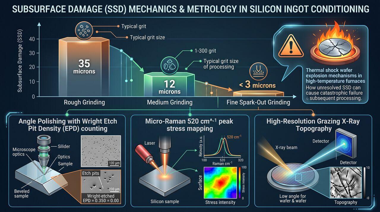
To validate fine grinding recipe performance and guarantee zero microcrack propagation into downstream wafering, fab metrology labs employ three quantitative SSD measurement techniques:
Comparative SSD Profiles Across Conditioning Stages
06Yield Impact & Downstream Process Interactions
The depth and density of residual SSD following ingot conditioning directly govern mechanical wafer breakage probability in subsequent manufacturing steps:
- Multi-Wire Slicing Initiation Sites: Residual deep cracks on the ingot outer cylinder act as stress concentration notches when the wire saw enters the block, causing edge-chipping and wafer micro-cleavage.
- Thermal Shock Vulnerability: During high-temperature diffusion or thermal oxidation (), localized thermal expansion stresses around unetched SSD microcracks exceed Mode-I fracture toughness (), triggering catastrophic brittle wafer explosion inside vertical furnaces.
- Remediation Requirement: Fine cylindrical grinding recipes must systematically reduce below the total chemical etch removal allowance () allocated during post-lapping chemical etching.
→Prerequisites & continue reading
Prerequisites: Ingot Conditioning Kinematics (Tier 2), Solid State Physics, Advanced Mechanics of Materials
Also in Topic 2.1, Ingot Mechanical Processing & Geometric Conditioning:
Tier 1 · Ingot Conditioning Fundamentals: Cropping, Cylindric…Tier 2 · Ingot Conditioning Kinematics: CNC Cylindrical Grind…