01Tool Architecture of Industrial Multi-Wire Sawing Systems
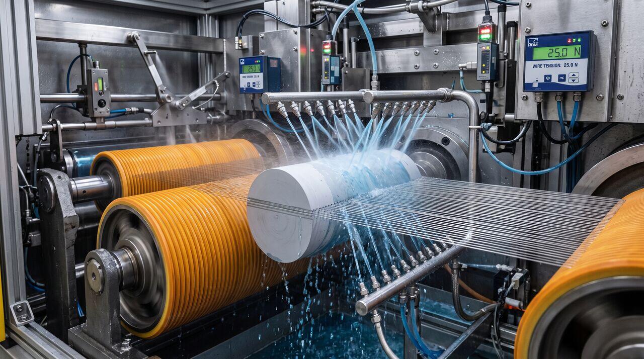
Industrial multi-wire saws are heavy-duty precision machines designed to maintain high wire speeds (), continuous high wire tension (), and sub-micrometer positioning accuracy under high mechanical loads.
Key Functional Subsystems
- Grooved Main Guide Rollers (Grooved Rollers): Highly rigid steel shafts covered with synthetic polyurethane or reaction-bonded silicon carbide coatings, precision-machined with thousands of V-grooves at exact pitch intervals ( pitch for wafers).
- Wire Propulsion & Spindle Drives: Direct-drive AC servo motors powering the main rollers to achieve rapid acceleration ( in ) and high-frequency bi-directional reciprocating motion.
- Closed-Loop Dynamic Wire Tensioners: Low-inertia pneumatic or magnetic dancing-arm assemblies equipped with optical encoders and piezoelectric load cells to suppress high-frequency wire tension spikes.
- Ingot Down-Feed Axis: Linear motor drive table with sub-micron feedback resolution, driving the silicon ingot downward into the wire web at precise feed rates ().
02Wire Movement Kinematics: Reciprocating Motion vs. Continuous Spooling
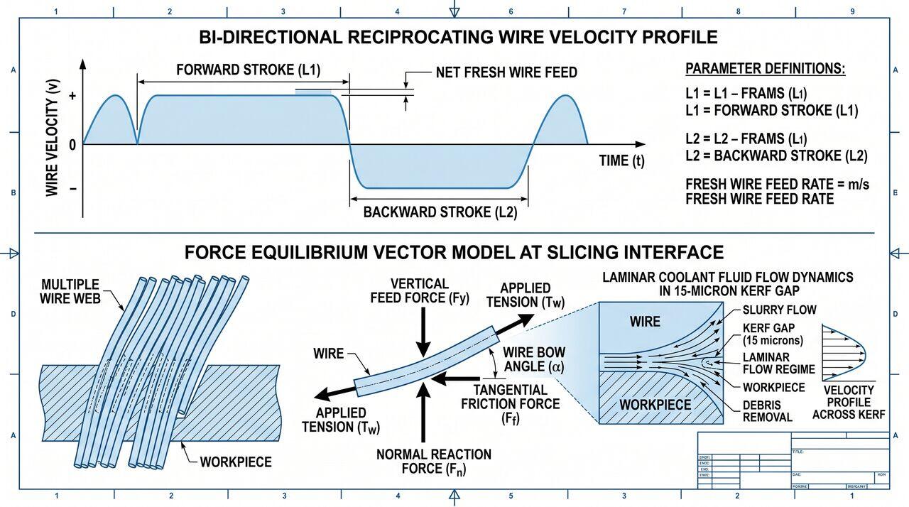
To prevent localized wire wear and ensure uniform diamond grain engagement across the entire ingot length, modern wire saws utilize a bi-directional reciprocating wire movement profile.
Kinematic Motion Profile
- Forward Movement (): Wire moves forward at for a set length ().
- Deceleration & Reversal: Wire rapidly decelerates to and reverses direction.
- Backward Movement (): Wire moves in reverse at for a shorter distance ().
- Net Fresh Wire Consumption (): With every cycle, a net of fresh diamond wire is unwound from the supply spool and permanently collected on the take-up spool.
This net replenishment continuously introduces sharp, un-worn diamond abrasives into the cutting zone while maintaining identical tension profiles across the entire wire web grid.
03Dynamic Wire Tension Control & Vibration Damping
Wire tension () is the most critical operational variable governing wafer Total Thickness Variation (TTV), Bow, and Warp.
Force Equilibrium at the Cutting Interface
When the silicon ingot pushes downward into the tensioned wire, the wire deflects, forming a characteristic Wire Bow Angle (). The vertical cutting force () is balanced by the wire tension ():
Where:
- = Applied wire tension ().
- = Wire bow angle ().
- = Normal down-feed cutting force.
Tension Instability Failure Modes
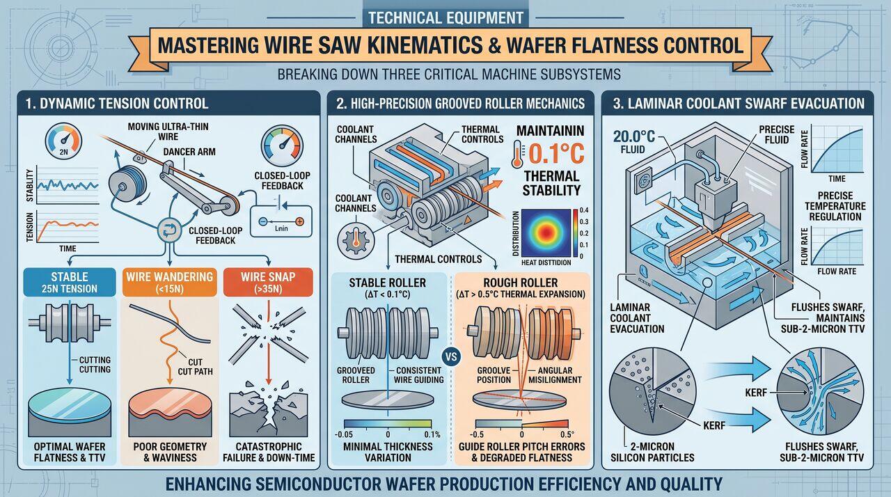
- Excessive Wire Tension (): Exceeds the yield strength of the ultra-thin steel wire core ( core diameter with tensile strength ), causing catastrophic wire snap mid-cut!
- Insufficient Wire Tension (): Increases wire bow angle (), leading to severe wire lateral wandering, high Total Thickness Variation (TTV), and wavy wafer surface topography.
- Resonant Wire Vibration: Transverse acoustic wire waves triggered by guide roller rotation can cause periodic thickness striations on the wafer surface known as saw marks or wavy kerf.
04Coolant Hydrodynamics & Swarf Evacuation Physics
Unlike free abrasive slurry sawing which relies on viscous oil vehicles, fixed diamond wire sawing uses water-based synthetic coolant solutions optimized for high heat capacity and ultra-fast swarf flushing.
Hydrodynamic Flow Mechanics in the Kerf
The gap between the cutting wire and the silicon sidewall is extremely narrow, typically only wide.
- Reynolds Number in the Kerf: Flow within the narrow cutting kerf is laminar (Re < 500), dominated by viscous boundary layer drag along the rapidly moving wire surface.
- Coolant Temperature Control: The friction generated by millions of diamond particles scratching silicon at releases kilowatts of thermal energy. Coolant fluid temperature is regulated at . A temperature rise across the wire web causes thermal expansion of the guide rollers, introducing a pitch error that ruins wafer TTV!
Swarf Evacuation Efficiency
Silicon swarf particles ( diameter) must be swept out of the kerf immediately. If swarf accumulates in the cut gap:
- It causes secondary abrasive wear on the wafer sidewalls, increasing subsurface damage depth.
- It increases viscous drag forces, leading to localized wire heating and wire wandering.
05Operational Parameter Optimization Matrix
| Operational Variable | Typical Range | Impact of Increasing Variable | Impact of Decreasing Variable |
|---|---|---|---|
| Wire Speed () | Reduces cutting force per grain; improves surface finish | Increases cutting force per grain; increases wire bow | |
| Ingot Feed Rate () | Increases slicing throughput; increases wire bow and TTV | Improves wafer flatness (TTV); reduces throughput | |
| Wire Tension () | Reduces wire bow; improves wafer flatness; higher wire snap risk | Increases wire wandering; causes high TTV and warp | |
| Net Wire Consumption | Maintains sharp diamonds; improves cut consistency | Lower wire cost; higher diamond wear and wire mark risk |
→Prerequisites & continue reading
Prerequisites: Multi-Wire Diamond Sawing Fundamentals (Tier 1)
Also in Topic 2.2, Multi-Wire Diamond Sawing & Wafer Slicing:
Tier 1 · Multi-Wire Diamond Sawing Fundamentals: How Ingot Bl…Tier 3 · Physics of Wire Sawing: Diamond-Silicon Micro-Scratc…