01Chemical Recirculation Loop Architecture
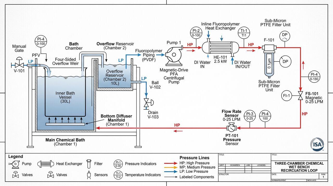
To maintain chemical purity, bath temperature stability, and precise concentration control, wet immersion benches utilize closed-loop chemical recirculation systems.
02Core Plumbing Components
A. High-Purity Fluoropolymer Materials
All fluid-wetted components in advanced wet processing tools are constructed from high-purity fluoropolymers to eliminate metallic leaching and chemical degradation:
- PFA (Perfluoroalkoxy): Used for transparent chemical tubing, fittings, and valve bodies.
- PTFE (Polytetrafluoroethylene): Used for filter housings, pump diaphragms, and tank liners.
- PVDF (Polyvinylidene Fluoride): Used for ambient DI water piping manifolds.
B. Magnetic-Drive PFA Pumps
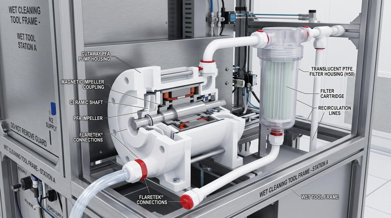
Standard mechanical shaft seals leak and shed particles. Wet tools utilize magnetic-drive seal-less pumps or pneumatically driven dual-diaphragm PFA pumps. Magnetic coupling isolates the motor drive from the fluid chamber, ensuring zero particle generation.
C. Sub-Micron Filtration
Recirculation loops feature PTFE membrane filter cartridges with pore ratings down to (). Filters operate under constant flow to continuously capture micro-particles before they can redeposition on wafer surfaces.
03Fluid Dynamics of Immersion Vessels: Weir Flow Mechanics
Uniform chemical bath flow is achieved using Overflow Weir Vessel Designs:
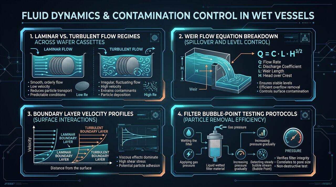
Where Q is fluid flow rate, is discharge coefficient, L is weir length, and H is head height over the weir crest.
Fluid enters the inner vessel bottom through perforated diffuser plates, flows upward past wafers, spills evenly over four perimeter weir edges into an outer collection trough, and drains into the recirculation pump reservoir. This eliminates stagnant liquid pockets and guarantees uniform temperature ().
04Hardware System Specifications Summary
| Component | Material | Operational Limits | Critical Failure Mode |
|---|---|---|---|
| Tubing / Fittings | PFA (High Purity) | Max , 0.6 MPa | Stress crack corrosion, O-ring degradation |
| Recirculation Pump | Mag-Drive PFA | Impeller cavitation, magnetic decoupling | |
| Filter Cartridge | PTFE Membrane () | Max | Membrane clogging, micro-bubble shedding |
| Heat Exchanger | PFA Tube Bundle | control | Chemical pinhole leaks into heating fluid |
→Prerequisites & continue reading
Prerequisites: Fluid Mechanics, Piping Systems, Wet Bench Fundamentals
Also in Topic 4.2, Wet Bench vs Single-Wafer Processing:
Tier 1 · Wet Bench vs. Single-Wafer Tools: Operational Fundam…Tier 3 · Boundary Layer Mechanics, Mass Transfer & Cross-Cont…