01Boundary Layer Fundamentals in Wet Processing
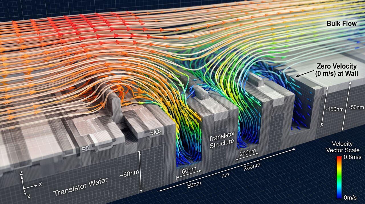
When liquid flows over a wafer, fluid velocity drops to zero directly at the solid surface due to the no-slip condition. This creates a Hydrodynamic Boundary Layer () and an inner Concentration Boundary Layer ().
Chemical reactants must diffuse across these boundary layers to reach the wafer surface, while etch byproducts and detached particles must diffuse outward.
02Mathematical Modeling of Boundary Layer Thickness
A. Flat Plate Laminar Flow (Immersion Bath)
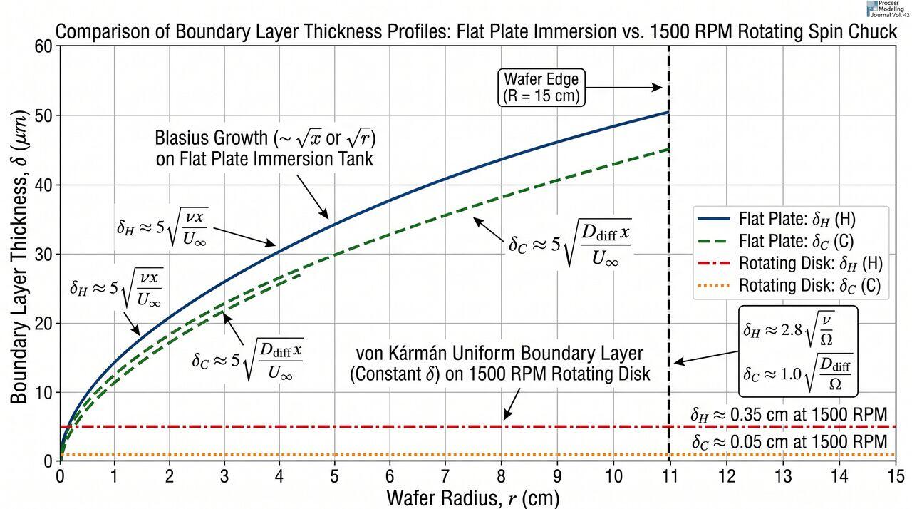
For fluid flowing at velocity across an immersed wafer, the hydrodynamic boundary layer thickness at distance x from the leading edge is governed by the Blasius solution:
Where is the local Reynolds number and is kinematic viscosity.
B. Rotating Disk Flow (Single-Wafer Spin Chuck)
For a wafer spinning at angular velocity in a single-wafer tool, the von Kármán exact solution proves that the boundary layer thickness is uniform across the entire wafer radius:
The concentration boundary layer thickness is related to by the Schmidt Number :
Where D is the molecular diffusion coefficient of active chemical species.
03Mass Transport & Reaction Rates
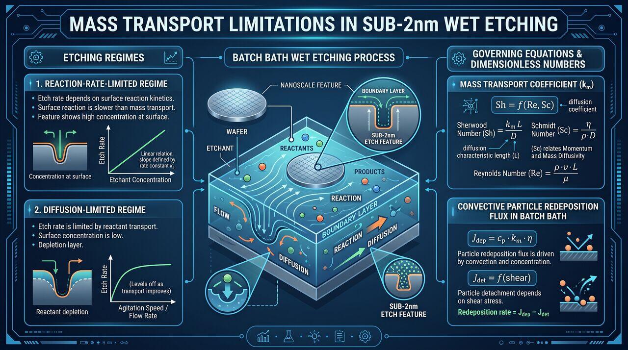
The overall reaction rate on the wafer surface is governed by the resistance of both chemical reaction kinetics () and mass transport boundary layer diffusion ():
In single-wafer tools operating at 1500 RPM, shrinks to , shifting the process into the reaction-rate-limited regime and maximizing chemical efficiency.
04Cross-Contamination Physics in Batch Processing
In immersion baths, particle re-deposition from liquid back to wafers is modeled by convective diffusion flux J:
Where is particle electrophoretic drift velocity governed by surface Zeta potentials (). If both particle and wafer surface possess identical charge polarities, repulsive electrostatic double-layer forces suppress redeposition even in shared batch tanks.
→Prerequisites & continue reading
Prerequisites: Navier-Stokes Equations, Transport Phenomena, Boundary Layer Theory
Also in Topic 4.2, Wet Bench vs Single-Wafer Processing:
Tier 1 · Wet Bench vs. Single-Wafer Tools: Operational Fundam…Tier 2 · Fluid Dynamics & Chemical Recirculation Hardware Arc…