01Executive Summary
In sub-2nm semiconductor manufacturing, yield loss during Chemical Mechanical Polishing is increasingly driven by sub-surface micro-scratching, chatter marks, and nano-corrosion. Eliminating these sub-nanometer defects requires mastering the colloidal physics of slurry suspensions and the non-linear viscoelastic mechanics of polyurethane pad asperities. This advanced monograph explores DLVO colloidal stability limits, slurry Large Particle Count (LPC) agglomeration kinetics, viscoelastic pad relaxation models, and sub-micron defect mitigation.
02DLVO Physics & Slurry Colloidal Stability
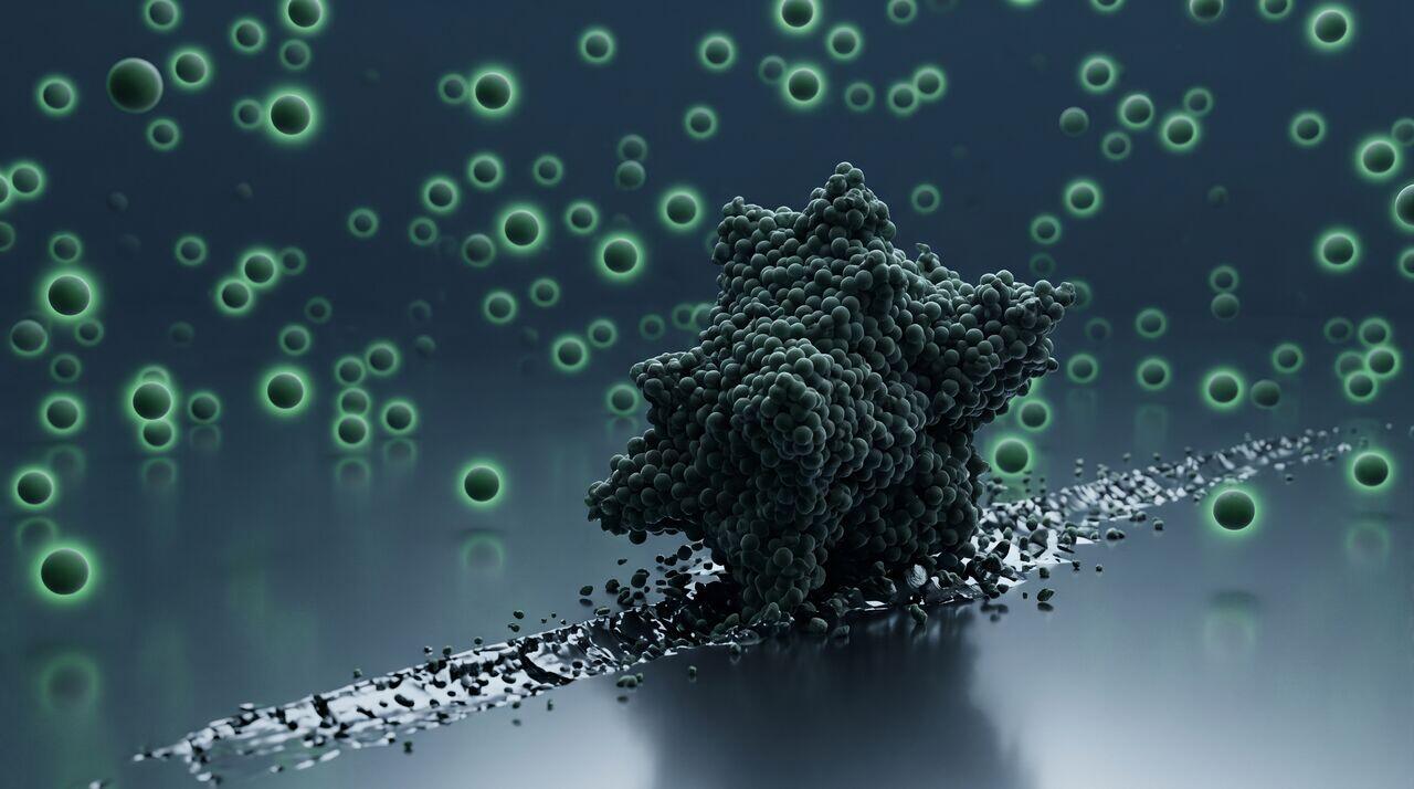
CMP slurries contain billions of nanoparticle abrasives () per milliliter. To prevent particles from irreversibly agglomerating into large aggregates () that cause severe wafer micro-scratching, the slurry suspension must maintain strong electrostatic and steric repulsion.
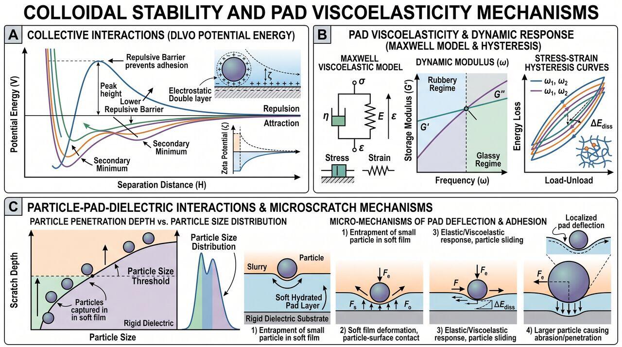
According to DLVO Theory (Derjaguin, Landau, Verwey, Overbeek), the total inter-particle interaction energy is the sum of attractive van der Waals forces () and repulsive Electrostatic Double Layer forces ():
Where:
- is the Zeta Potential (mV) of the abrasive particles.
- h is the inter-particle separation distance.
- is the inverse Debye screening length (proportional to ionic strength ).
- is the Hamaker constant ().
The Critical Zeta Potential Limit
To ensure a stable suspension with a high energy barrier (), the magnitude of the Zeta Potential must exceed :
- Stable Slurry Regime (): Strong electrostatic double-layer repulsion overcomes van der Waals attraction. Particles remain monodisperse.
- Unstable Agglomeration Regime (): Thermal collisions overcome the weak repulsive barrier, driving rapid particle coalescence into Large Particle Count (LPC) clusters ().
03Micro-Scratching Physics: Indentation by Agglomerates
When an agglomerated Large Particle (radius ) enters the pad-wafer interface, it experiences an abnormally high load because it protrudes above the surrounding monodisperse abrasive layer.
If the indentation depth caused by the agglomerate exceeds the thickness of the soft hydrated chemical surface film (), the particle penetrates into the rigid underlying silicon or dielectric crystal, initiating brittle plastic indentation micro-scratches:
04Viscoelastic Pad Asperity Kinetics
Polyurethane polishing pads are non-linear viscoelastic polymers. Under high-frequency cyclic loading () as asperities sweep across patterned wafer features, the pad response exhibits a time-dependent creep modulus E(t) modeled by the Generalized Maxwell Solid:
Where represents characteristic viscoelastic relaxation times.
If the tool rotational frequency matches the inverse viscoelastic relaxation time (), the pad transitions from flexible rubbery behavior to rigid glass-like behavior. This induces stick-slip friction instability, producing periodic chatter mark defects across thin-film gates.
05Defect Mitigation Engineering Matrix
| Defect Mechanism | Primary Physical Cause | Engineering Solution | Quantitative Target |
|---|---|---|---|
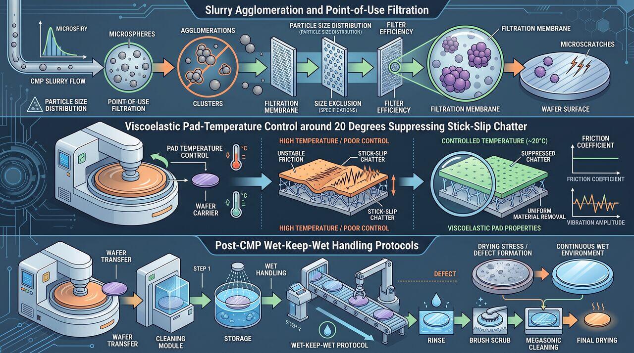
| Micro-Scratching | LPC slurry agglomerates () | Point-of-Use (POU) depth filtration & pH stabilization | LPC count |
| Chatter Marks | Viscoelastic stick-slip pad resonance | Temperature-controlled platen cooling () to shift | Friction coefficient fluctuation |
| Nano-Pitting | Localized chemical corrosion in slurry dead-zones | Post-CMP Megasonic wet cleaning with surfactant chemistry | Zero pinhole pits per wafer |
| Slurry Staining | Residual abrasive drying on wafer surface | Continuous wet-keep-wet wafer transfer handling | Post-CMP clean delay time |
→Prerequisites & continue reading
Prerequisites: ["p03-t3.3-t2-pad-conditioning-diamond-wear-endpoint-detection"]
Also in Topic 3.3, Slurry, Pad Conditioning & CMP Metrology:
Tier 1 · Slurry, Pad Conditioning & CMP Metrology Fundamental…Tier 2 · Pad Conditioning, Diamond Wear & Endpoint Metrology …